It’s Official! I completed my previous job (Matternet) on July 1st, and don’t start my next job (ABL Space Systems) until August 1st so I have some free time! Besides getting up to speed on my Velocity plane, and getting to Oshkosh with the boys, my goal is to complete the wing kit during this time off. The fuselage kit should be coming by the end of the month, and it will be a nice new chapter to start the fuselage when I start my new adventure at ABL. I will have approximately 15 days which I can focus exclusively on building. I think I might be able to do it. The items remaining in the wing kit is primarily completion and mounting of the Aileron and Flaps as well as all the flight control assemblies. Over the past few days I’ve been able to get a ton of time in, and have made quite a bit of progress towards completing the ailerons. Read on for the lengthy and detailed account of the activities so far.
Dimples, Dimples, and more Dimples
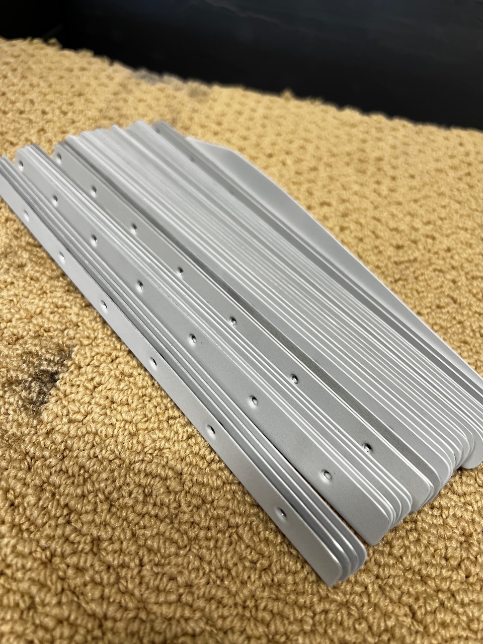
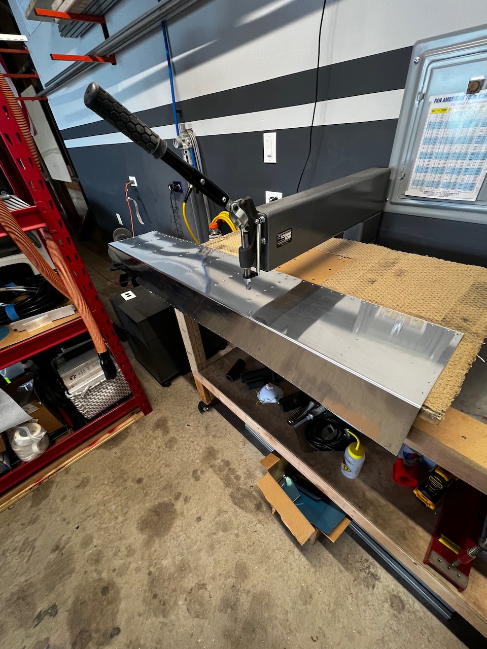
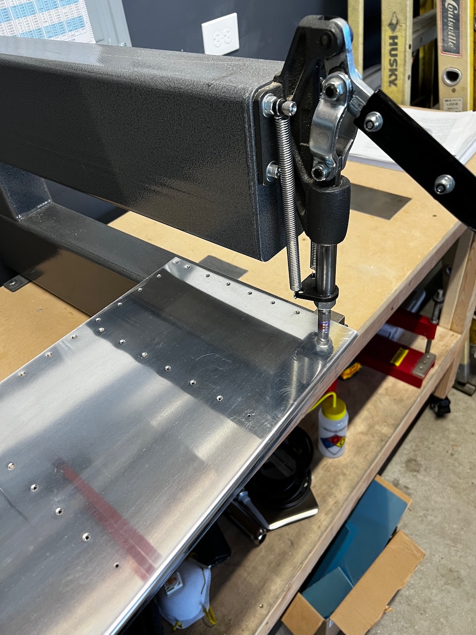
It started with a ton of dimpling. Probably 3+ hours in total. I had to dimple all the stiffeners and aft skins. Later I will dimple the ribs and leading edge. The only tricky thing was dimpling the holes near the trailing edge bend. The support table was getting in the way, but by removing that table, I was able to get it done.
Time to Dimple the Stiffeners…One down, infiniti to go!
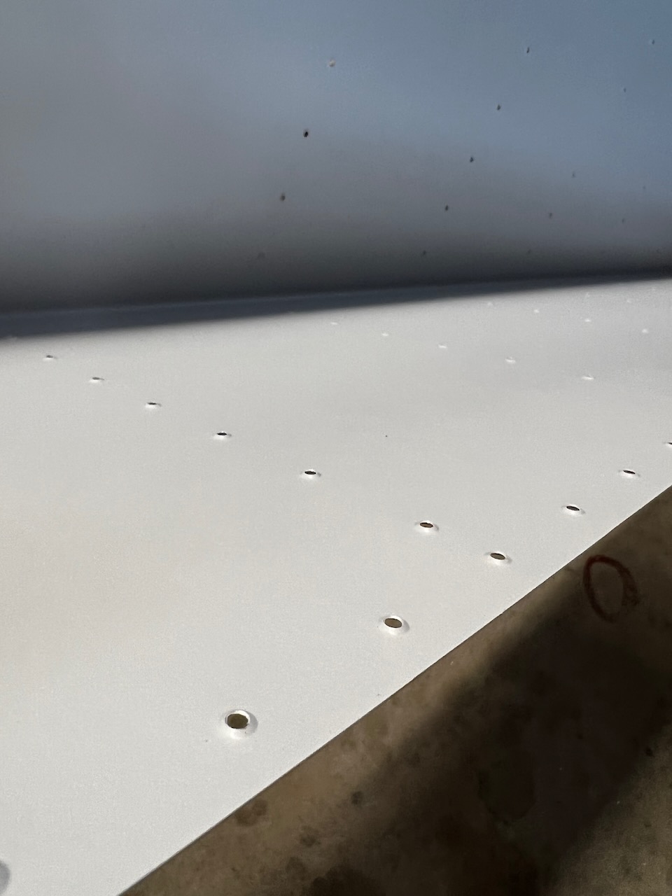
dimpling causing some paint flaking
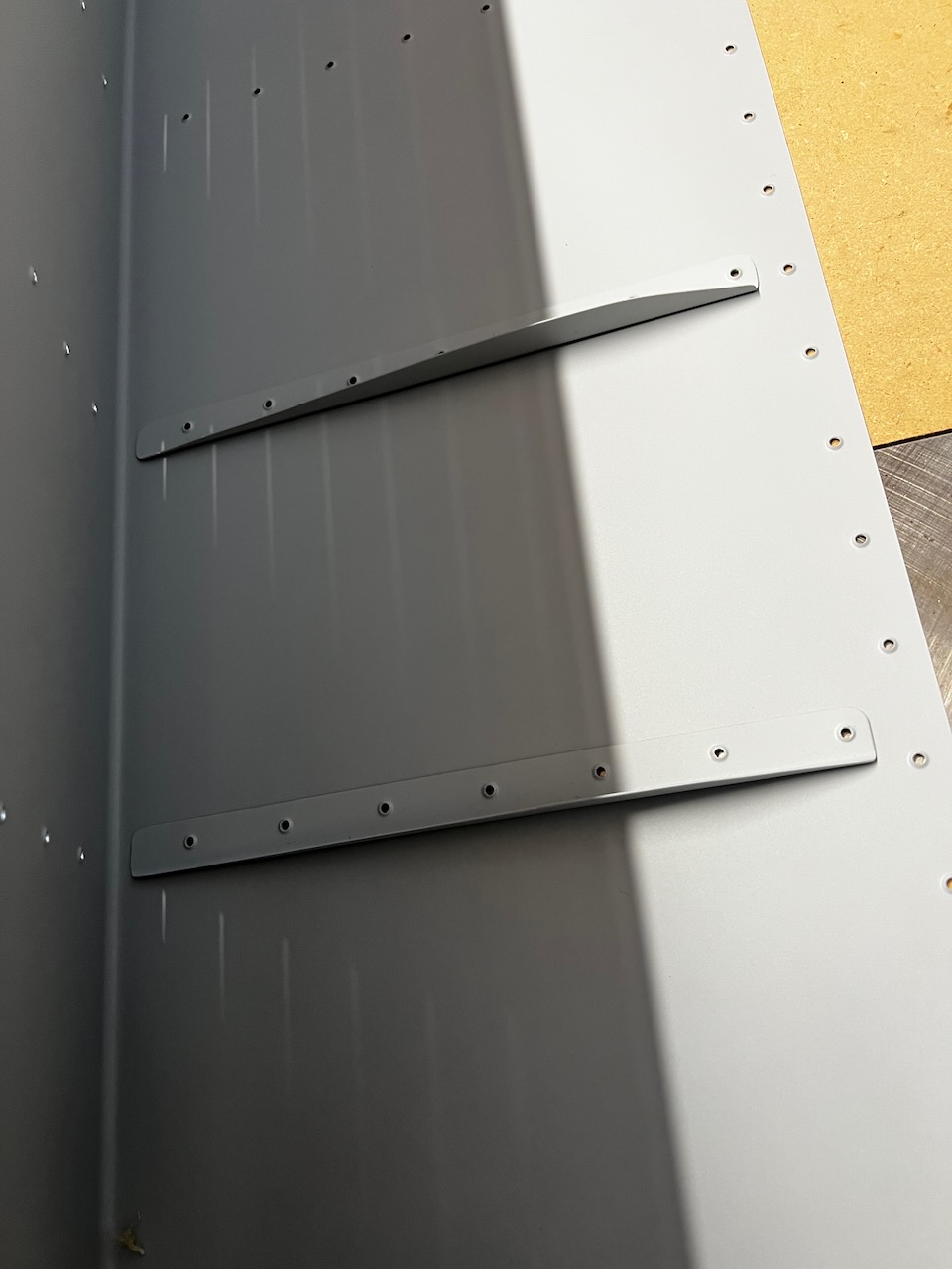
Stiffeners done!
Time to Dimple the Skins!
Near the bend, it’s hard to get the dimple done cleanly.
By removing the table makes it possible.
All done with Dimpling!
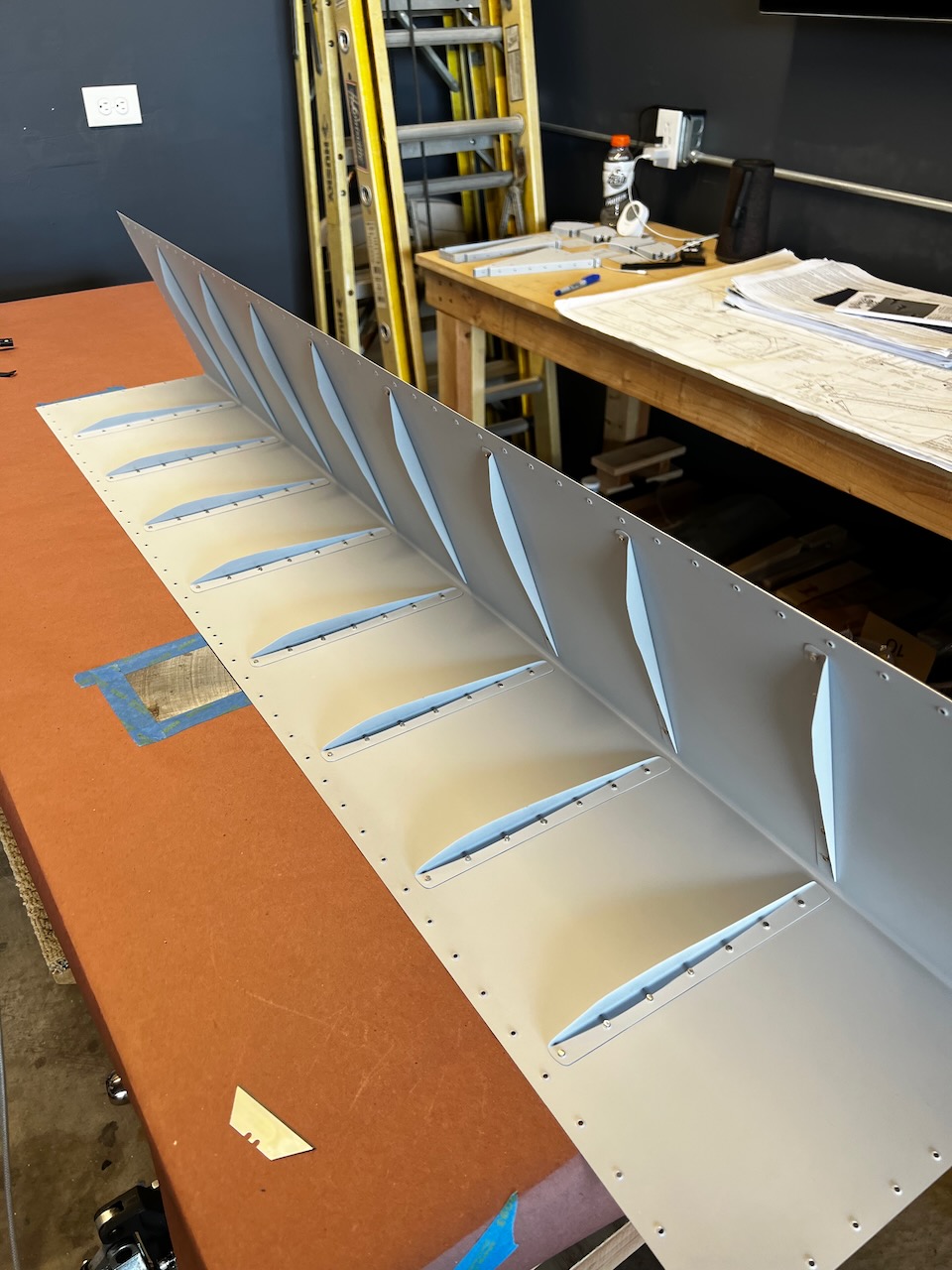
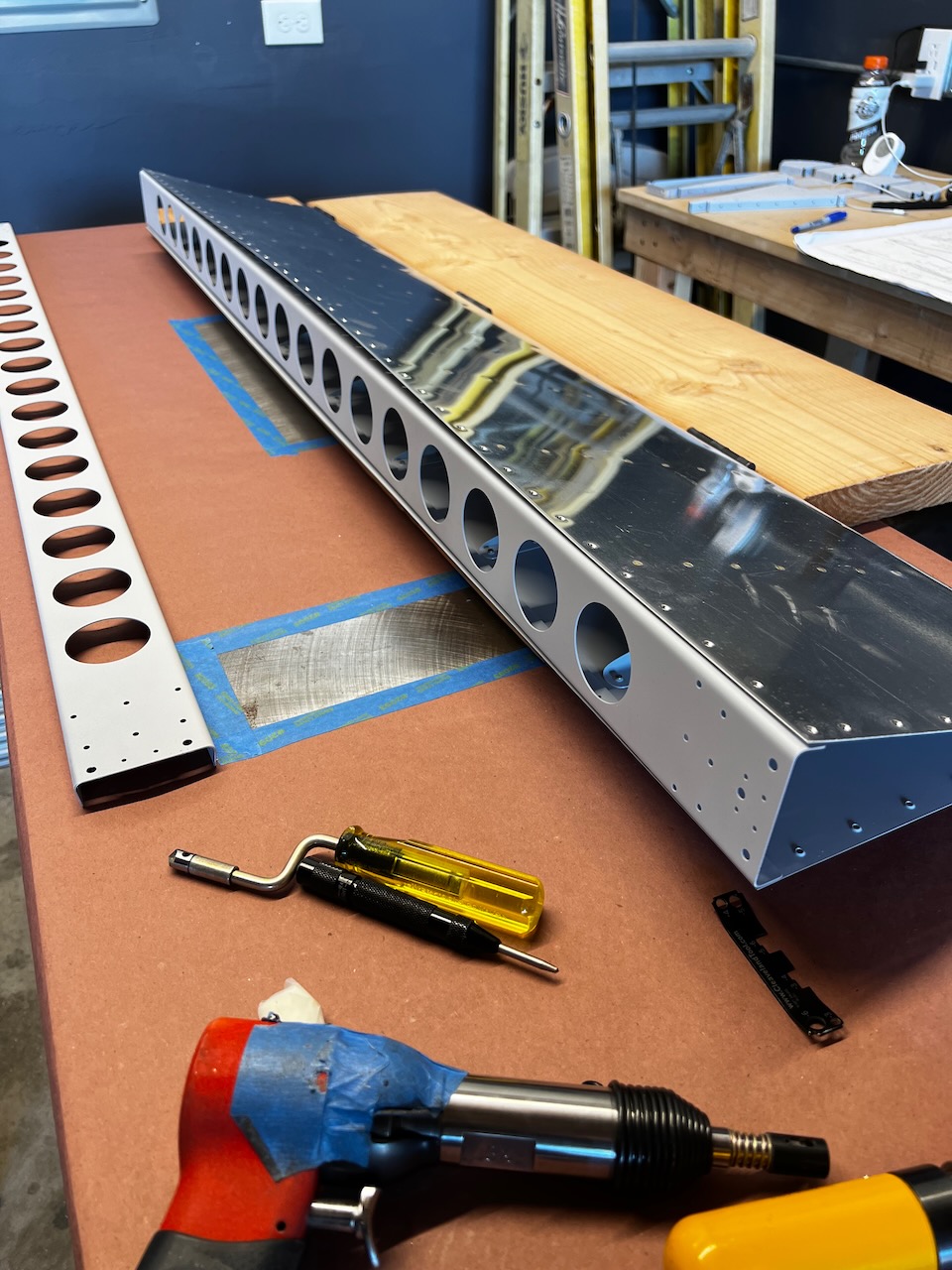
Back Riveting the Stiffeners
Next I needed to attach the stiffeners. The plans call for back riveting, which is pretty easy once I was all setup. The only surprise was how far back I had to bend the skins to get to the aft most rivets. This gets resolved in the next step when I bend the skins to the final shape.
Stiffeners need to be attached, but need to setup first.
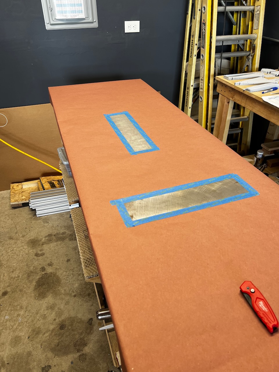
workbench setup for back riveting with a fresh top coat of butcher paper.
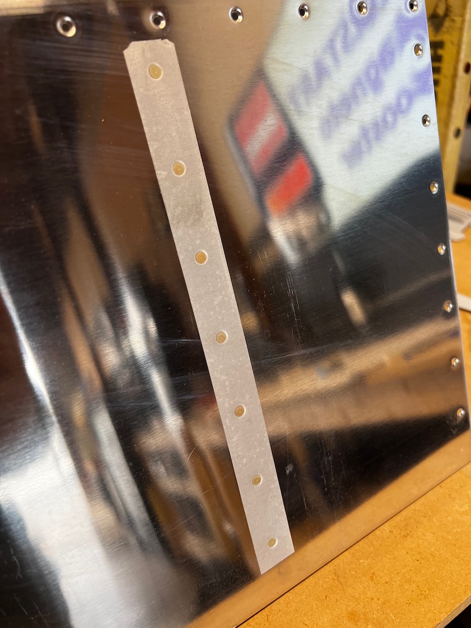
back riveting requires tape to hold the rivets in which using the rivet gun
all taped up!
rivets ready to recieving the stiffeners
Ready to rivet
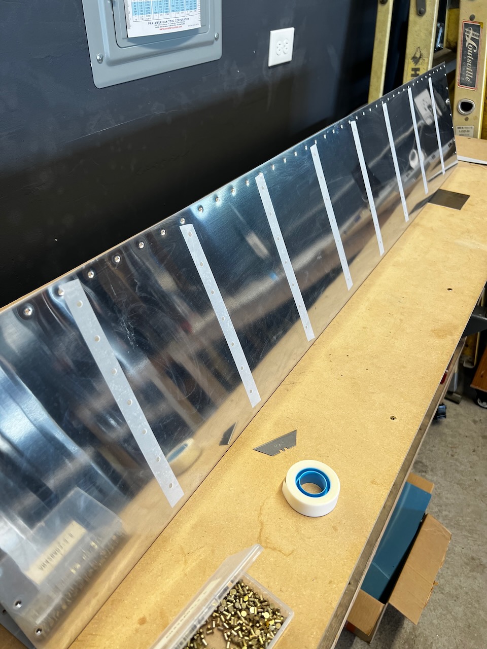
The skin requires quite a bit of opening up to be able to get to the aft most rivets
decent riveting job.
one side done, now time to rivet the other side
first skin done!
And both skins are done.
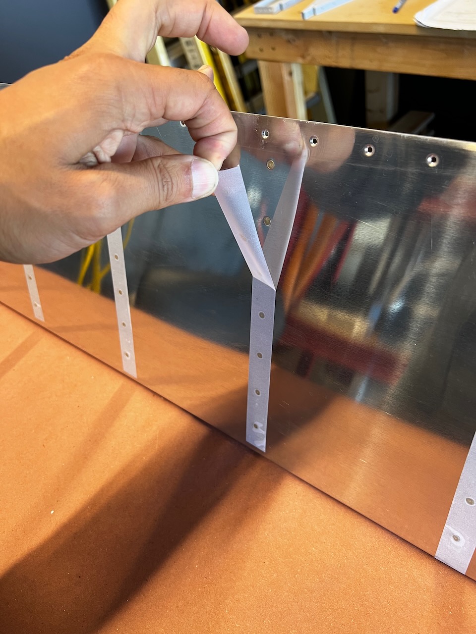
tape comes off and….
…ta da! Done!
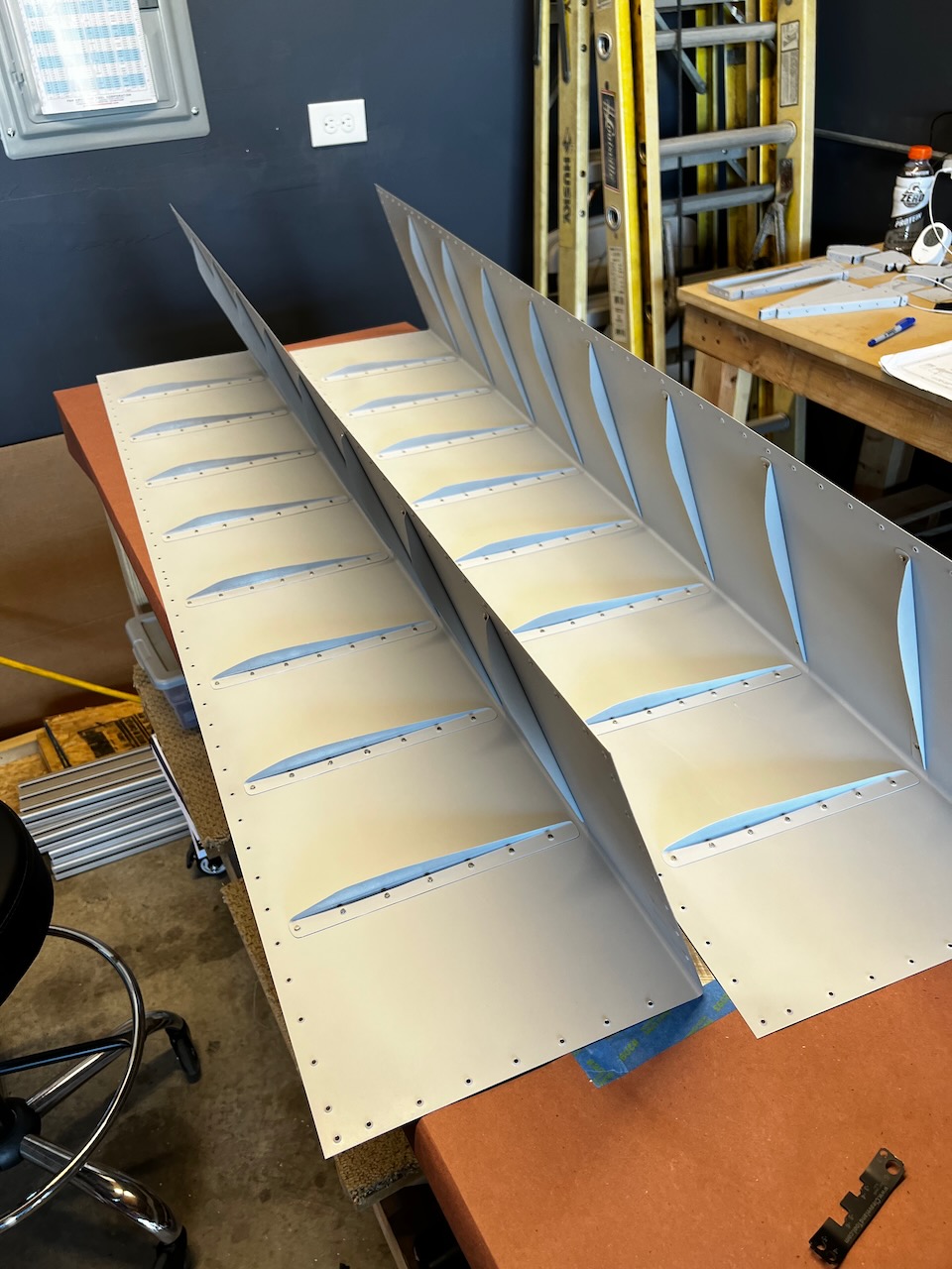
Skin Bending
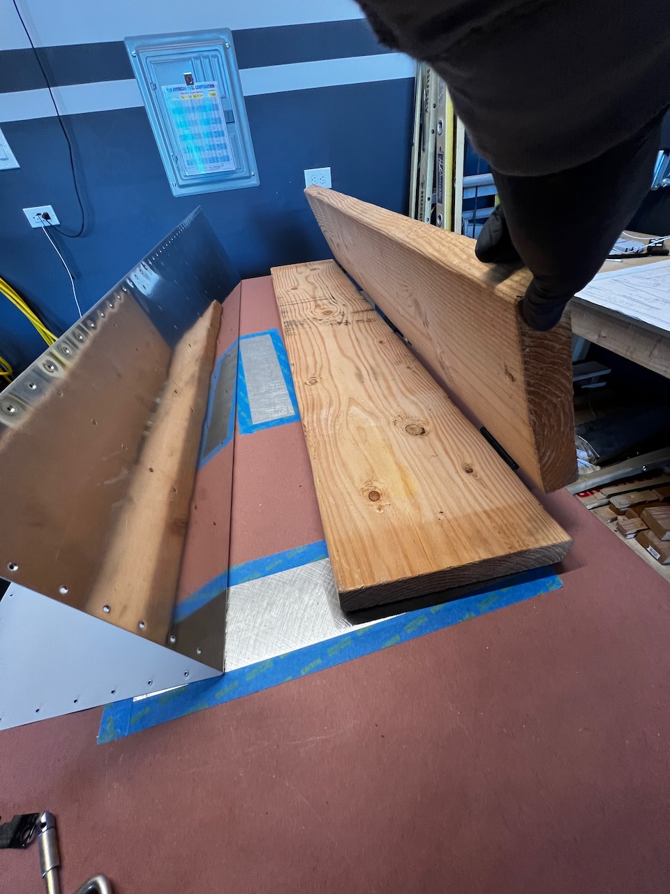
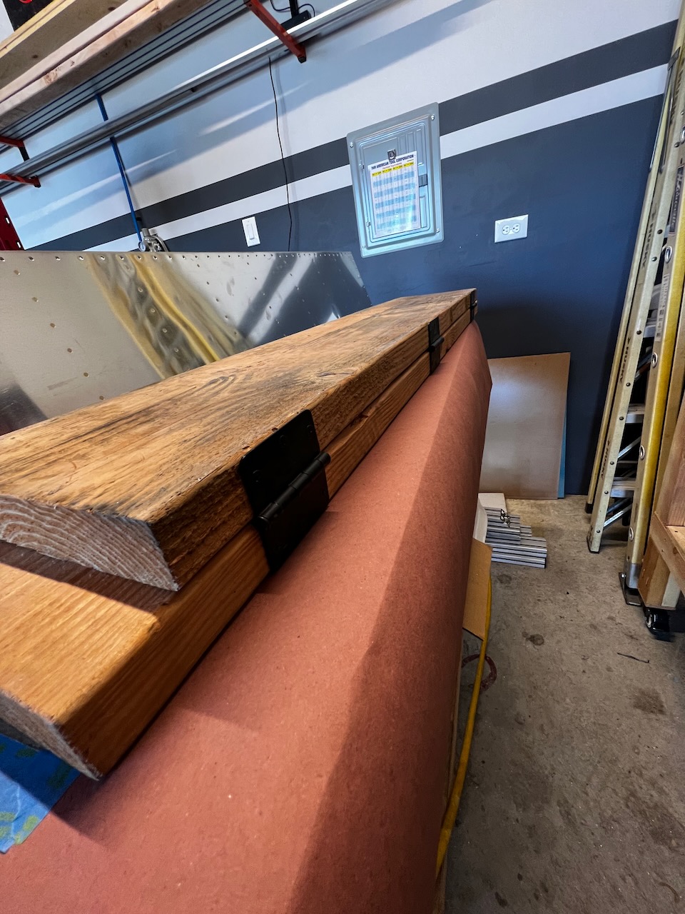
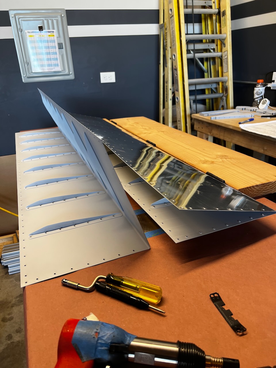
Thanks to Paul and Kacy, I didn’t need to build the skin bending jig. With their RV-7 complete, I was able to take a bunch of things they aren’t planning on using anymore. This jig is used to get the trailing edge bent enough so that it is the right height for the aileron spar. The reason it isn’t pre-bent to that angle is the need to install the stiffeners which require more space. The bending went well, and I ended up with two nicely straight skins with fairly accurate bend angles.
Bending Jig.
Hinged to allow the trailing edge to get bent properly
Once bent the skins should basically touch the spar
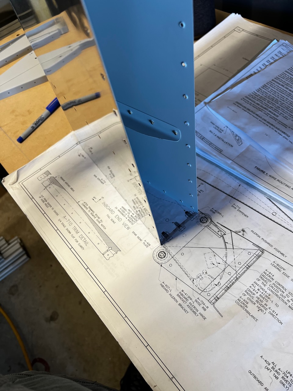
Plans allow you to approximate the bend using the full scale drawing
fits well!
One skin bent. Other skin not. Can you guess which is which? :).
Test Assembly
With the skins stiffened, I wanted to do a test fit of all the parts. It feels like there are a lot of steps, and a very specific order of operations that will result in not missing anything. This also allowed me to match drill and dimple a lot of parts. It was also time to attach the A-408 doublers to the spar. Easy Peasy. One new tool I got to use was the close quarter dimple dies needed to dimple the aft most holes of the main ribs. It gets really tight thus you can’t use the squeezer. See the pictures below.
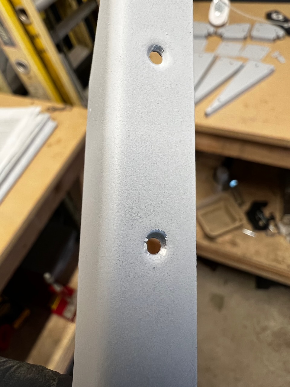
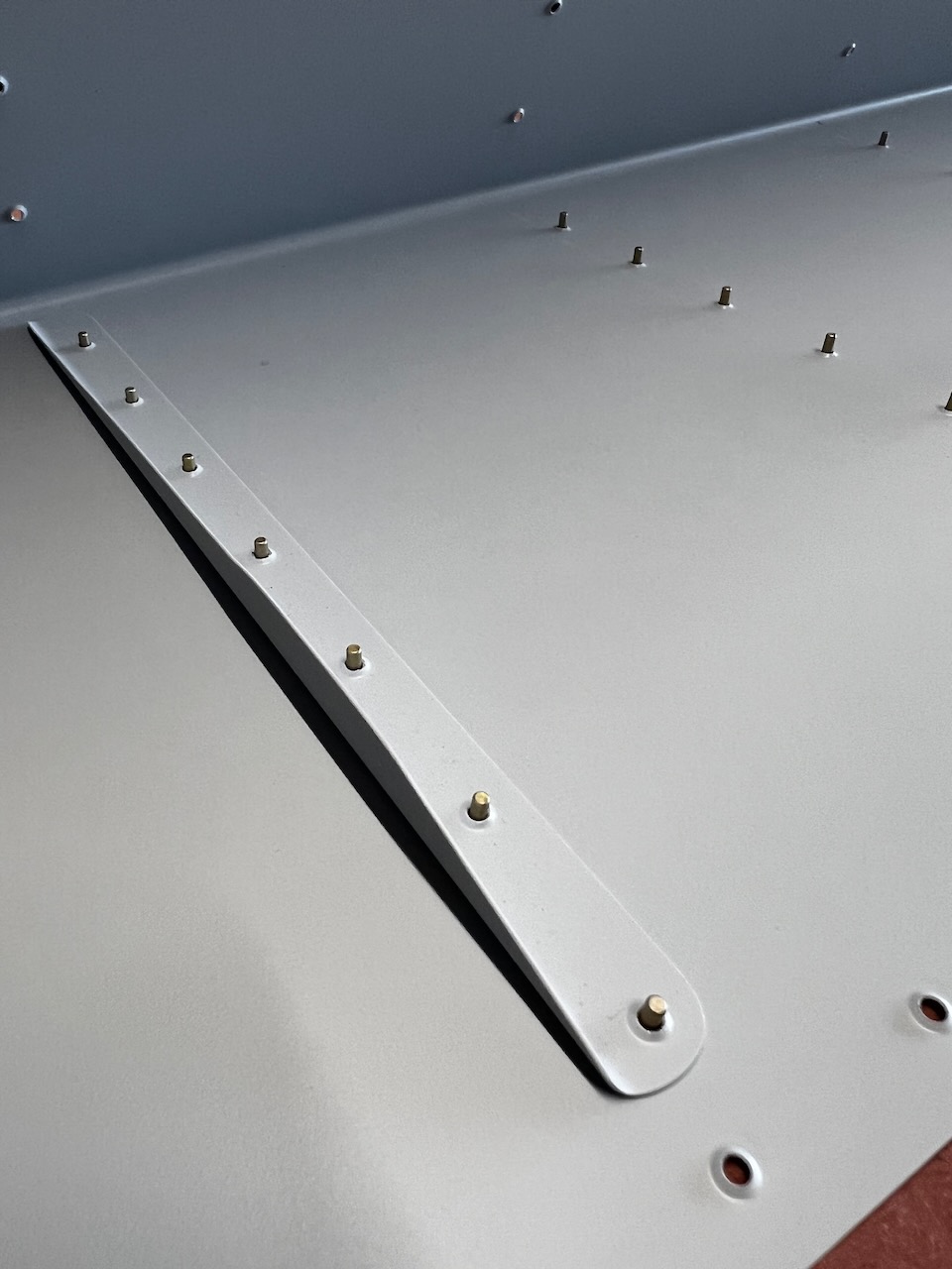
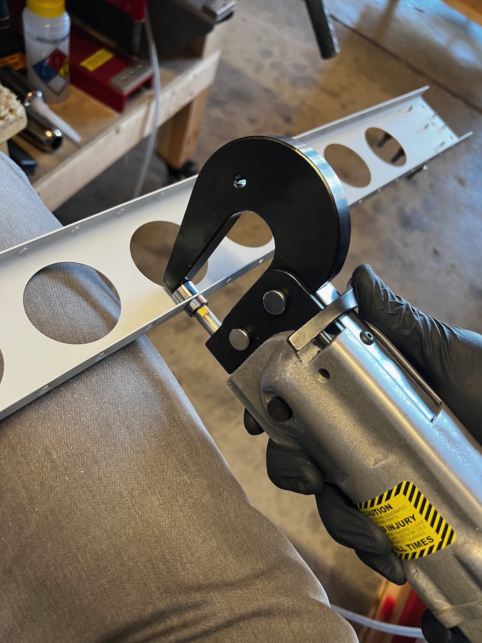
Dimpling the Aileron Spar
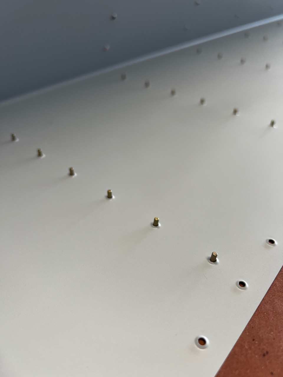
Expanding holes on bottom side to #30 to receive the CS4-4 blind rivets
dimpling for CS4-4 rivets
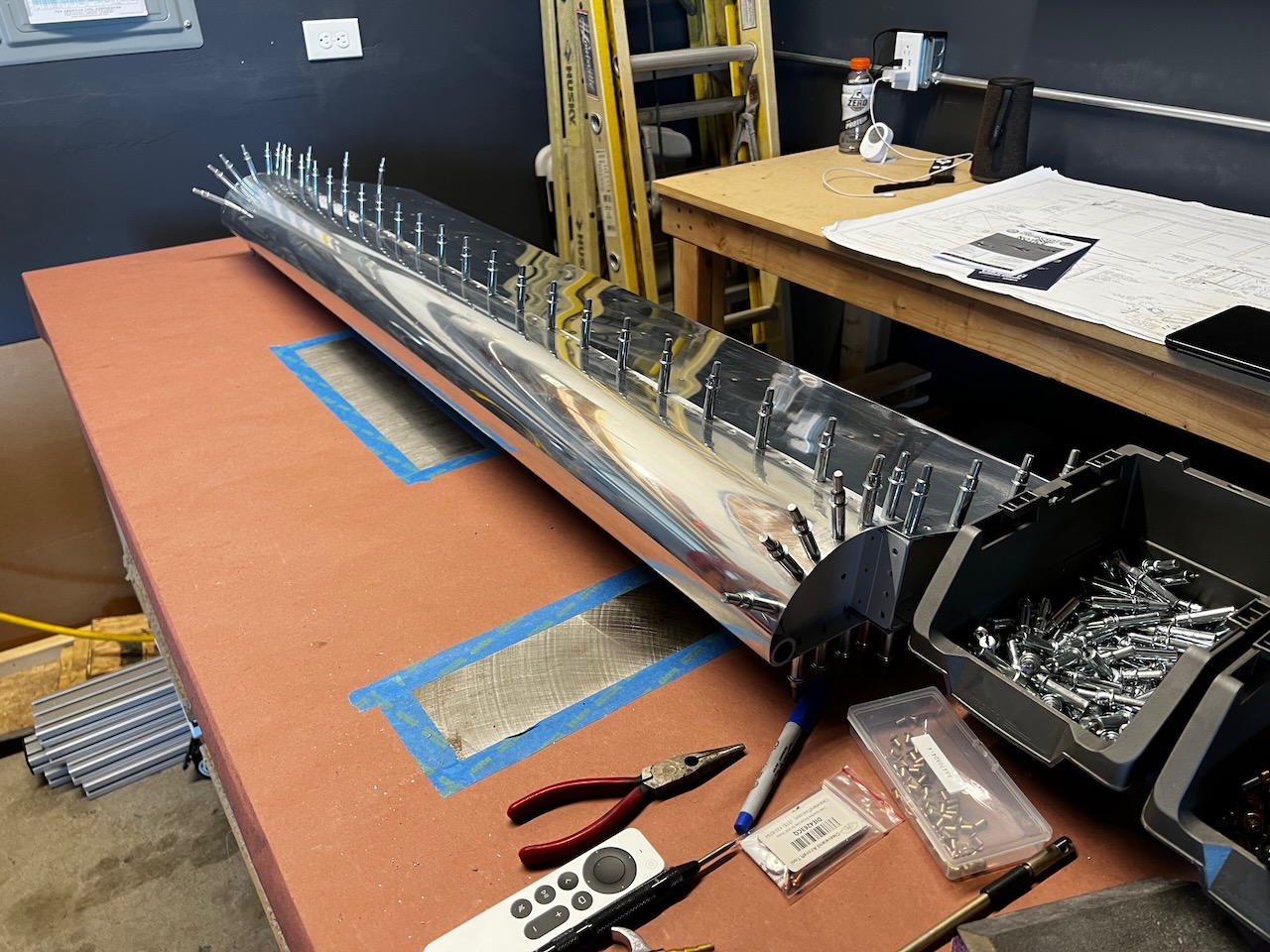
first test assembly of aileron
Looks like an aileron!
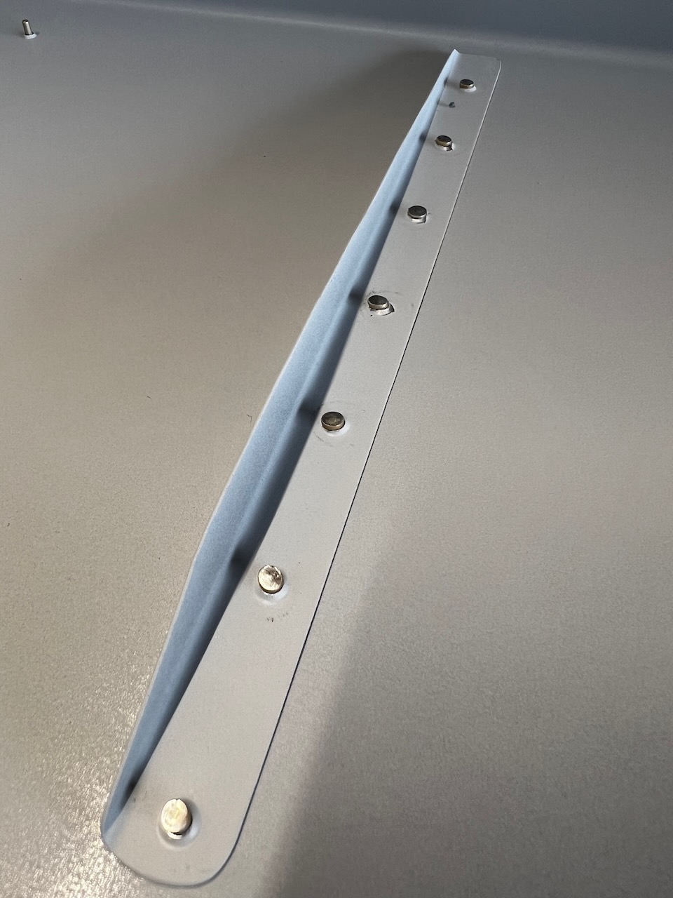
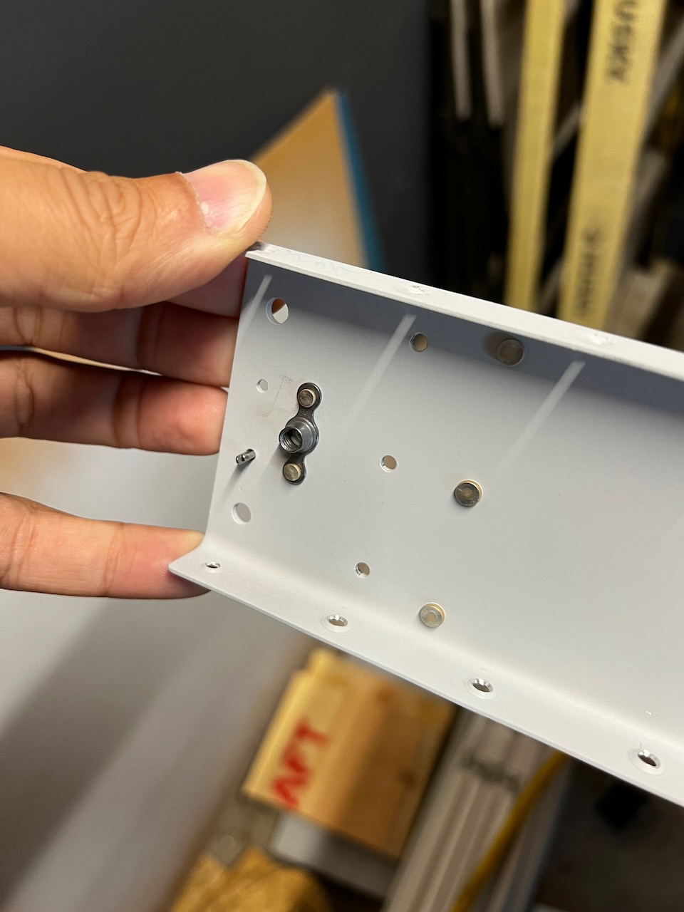
Riveting on the A-408 double plate
and attaching the nut plates
dimpling the aileron ribs
needed to use the close quarter rivet puller dimple die set
very cool tool
tight angle on the aft side made it difficult to get dies in
looks good!
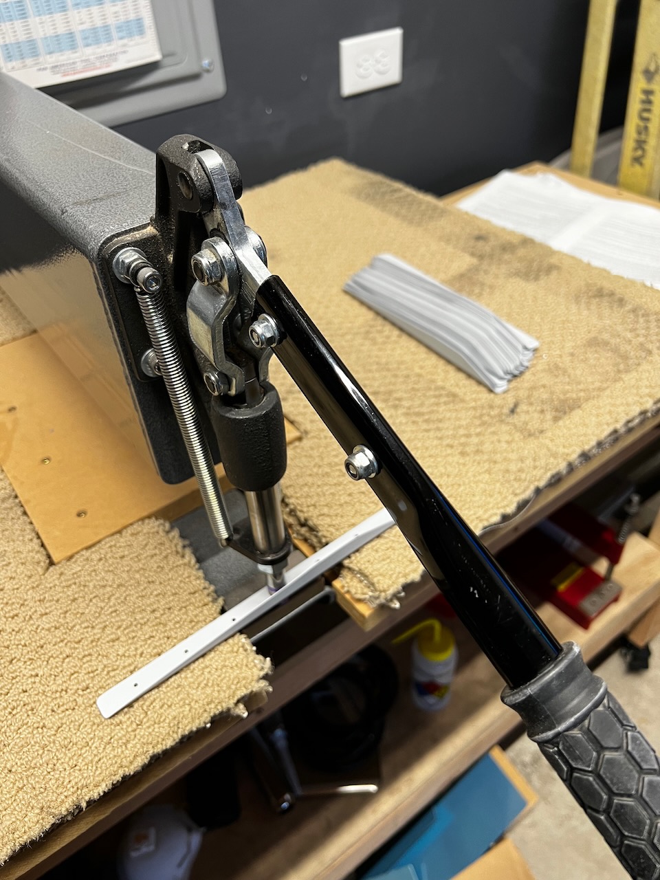
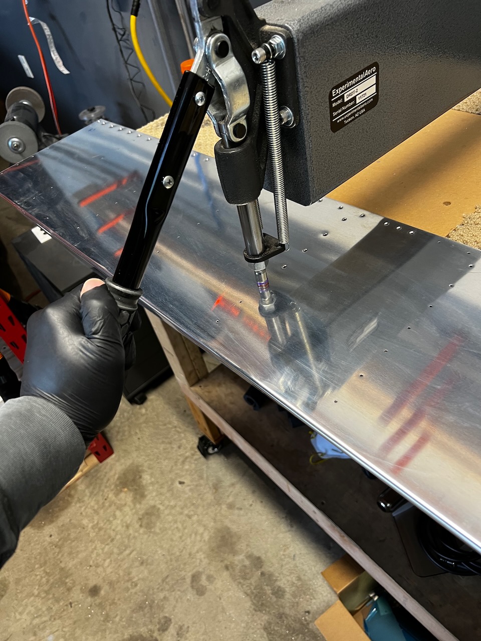
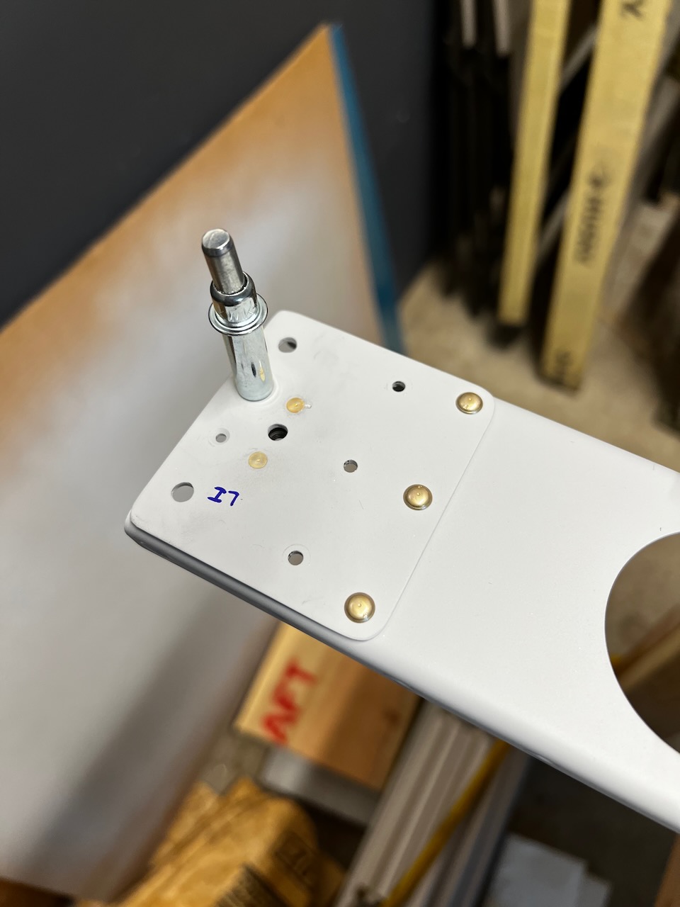
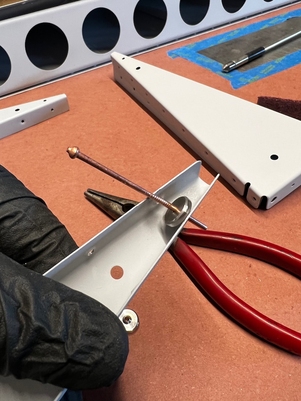
Counterbalance Match Drilling
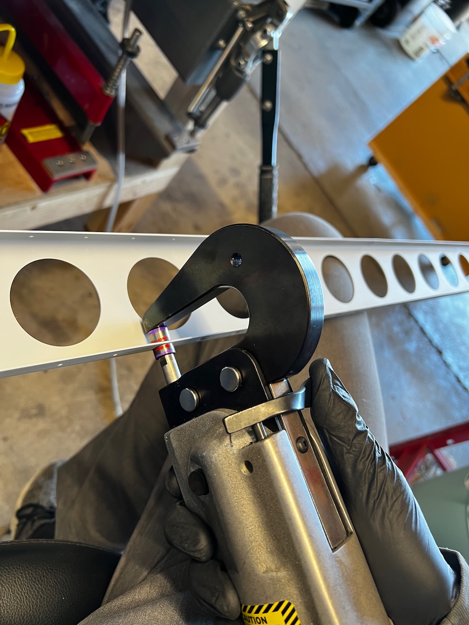
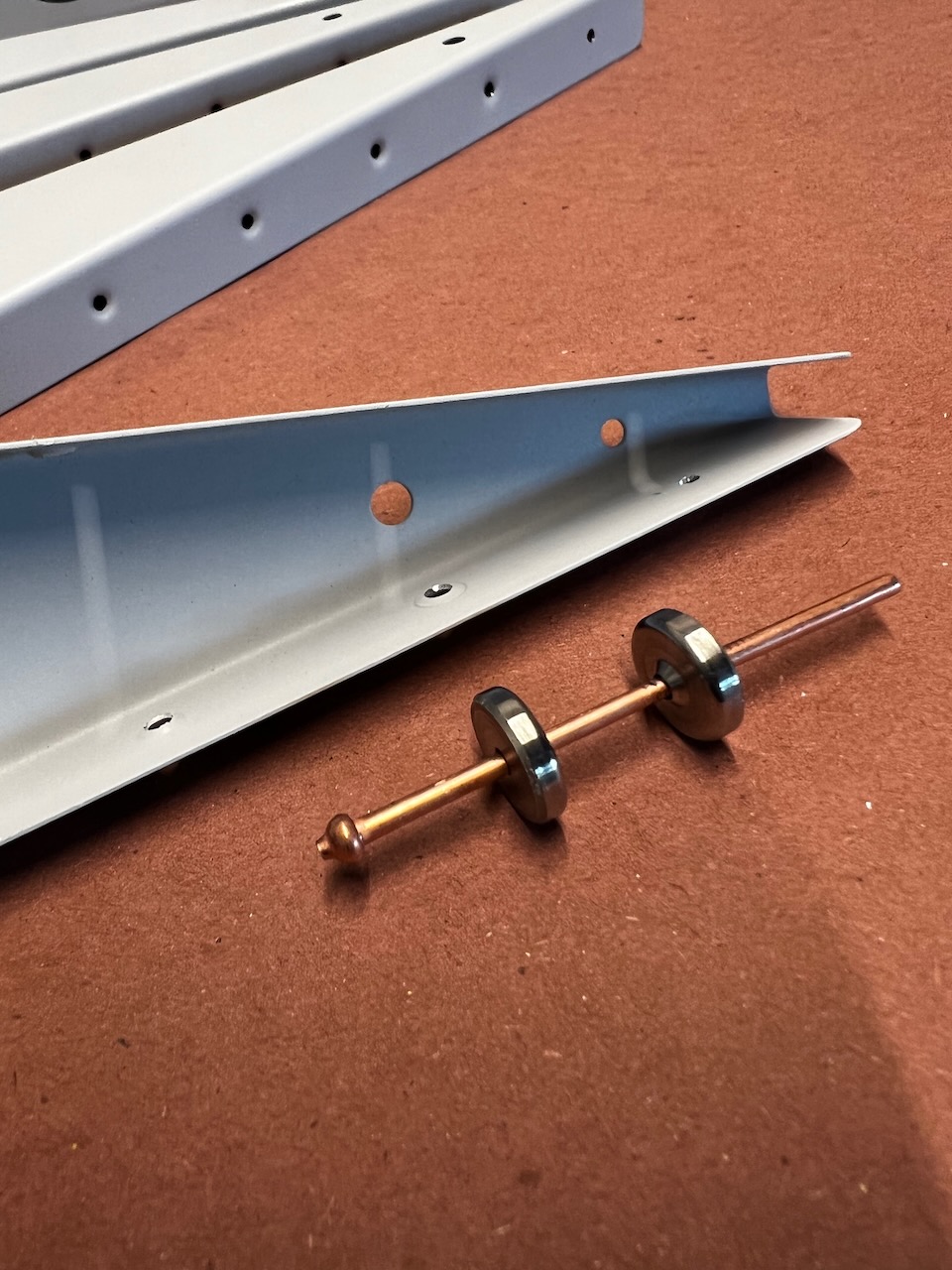
At the very front of the ailerons are heavy steel pipes that act as counterbalance pipes for balanced flight control authority. This pipe needs to be match drilled and countersunk for CS4-4 blind rivet attachment. It’s pretty straightforward, but takes a bit of time. Make sure you have a long 1/8″ drill bit to get the aft rivet match drill.
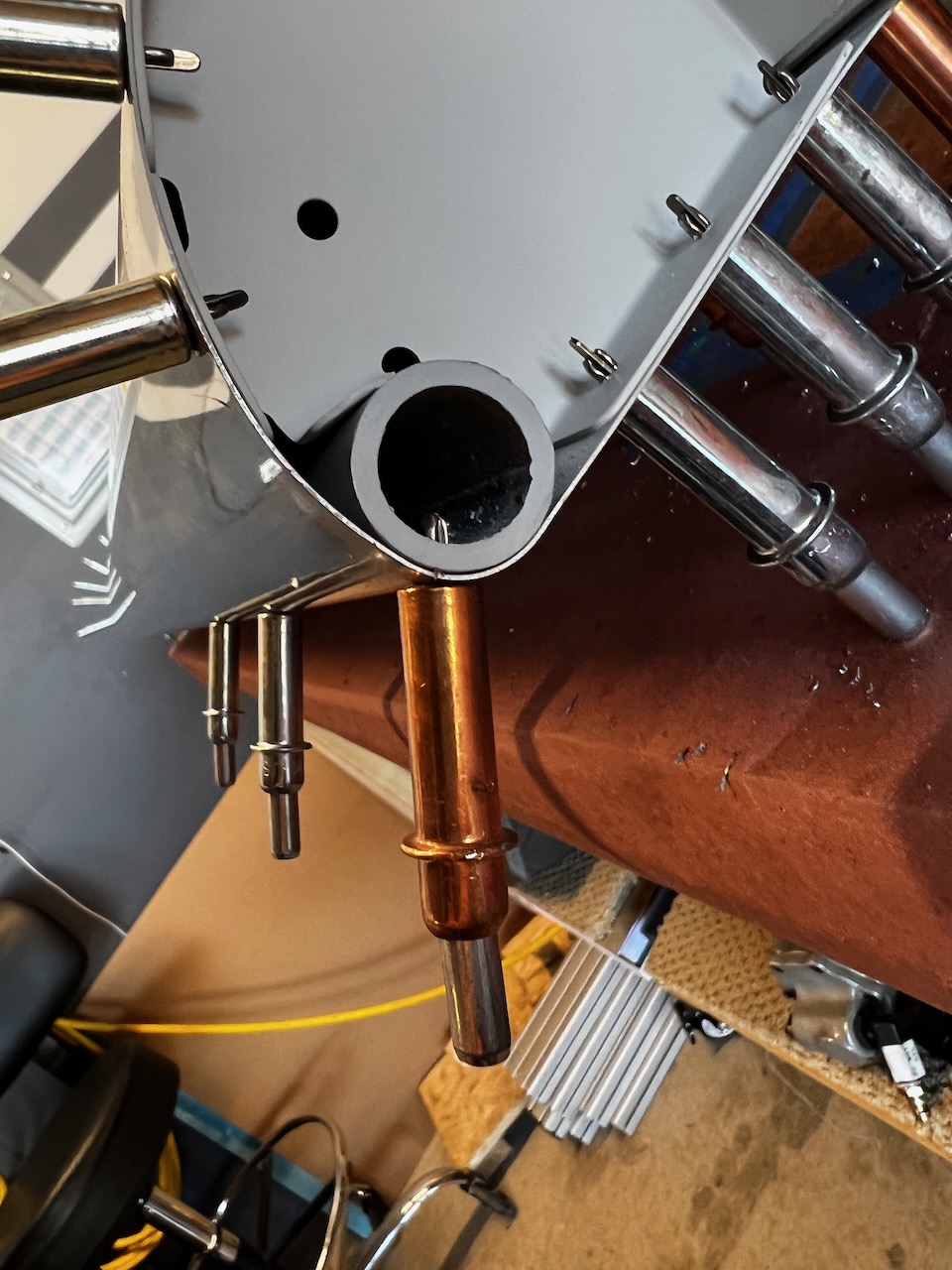
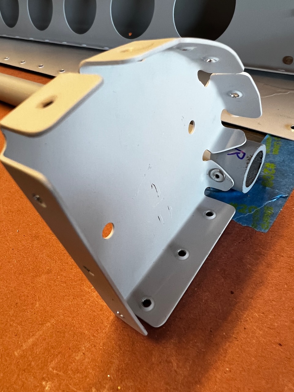
Counterbalance pipe fit
sits nicely in the pre-bent radius of the leading edge
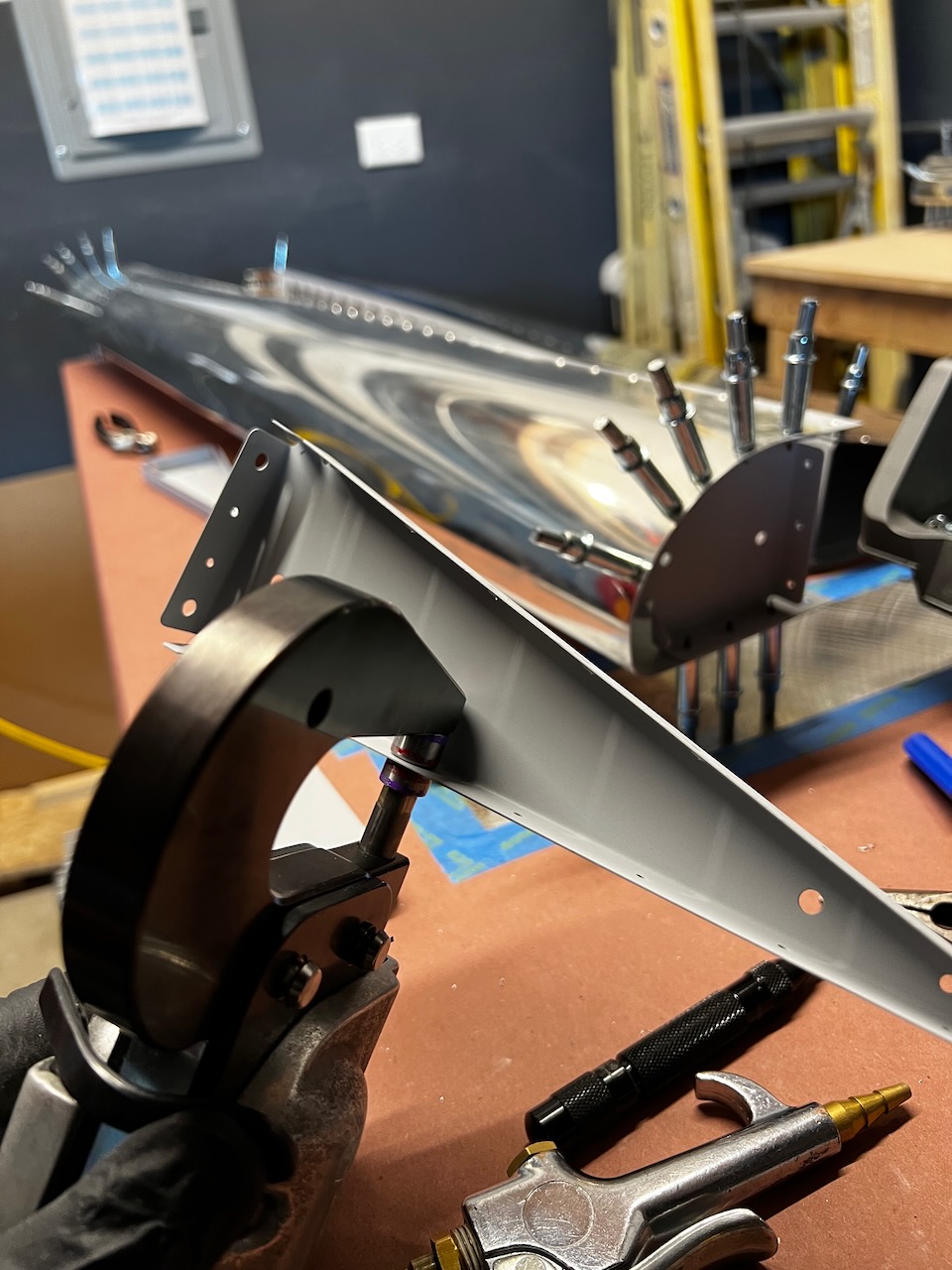
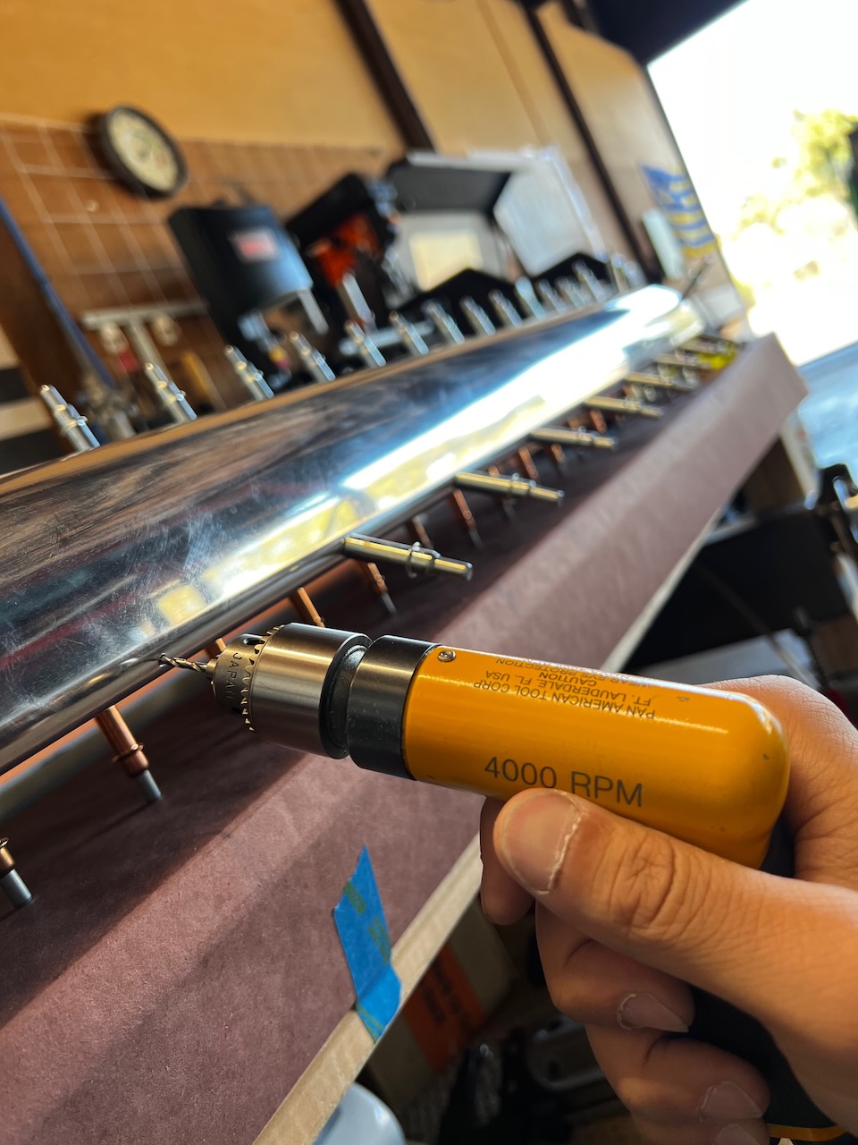
match drilling counterbalance with #30 drill bit
side view of the match drilling
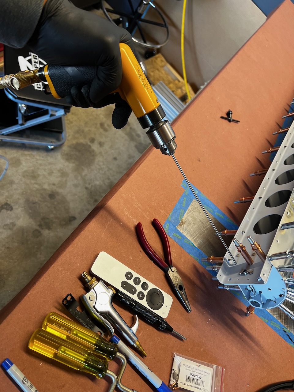
using the long bit to drill the after counterbalance hole
reaches perfectly!
aft hole complete
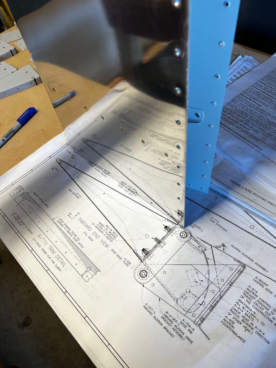
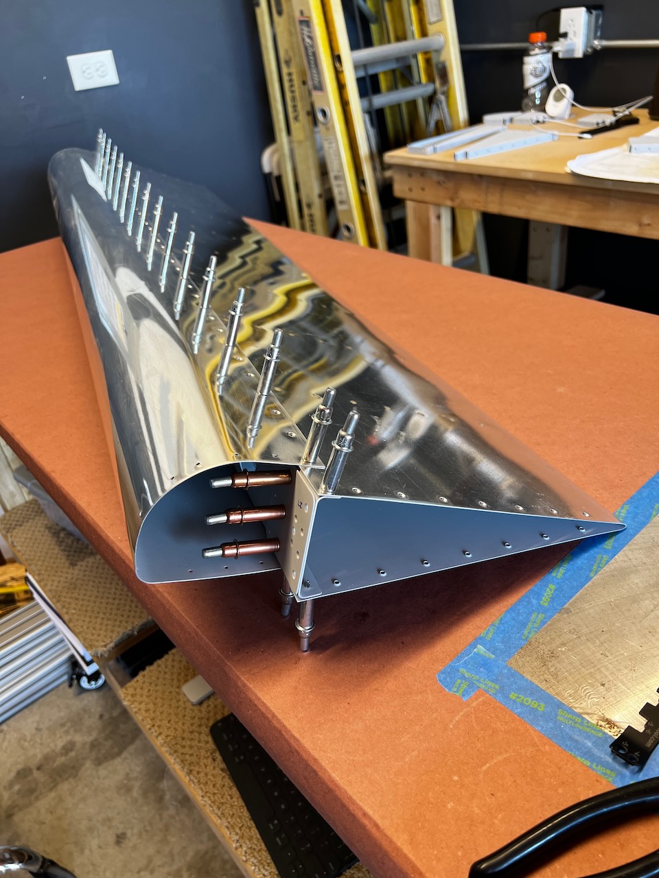
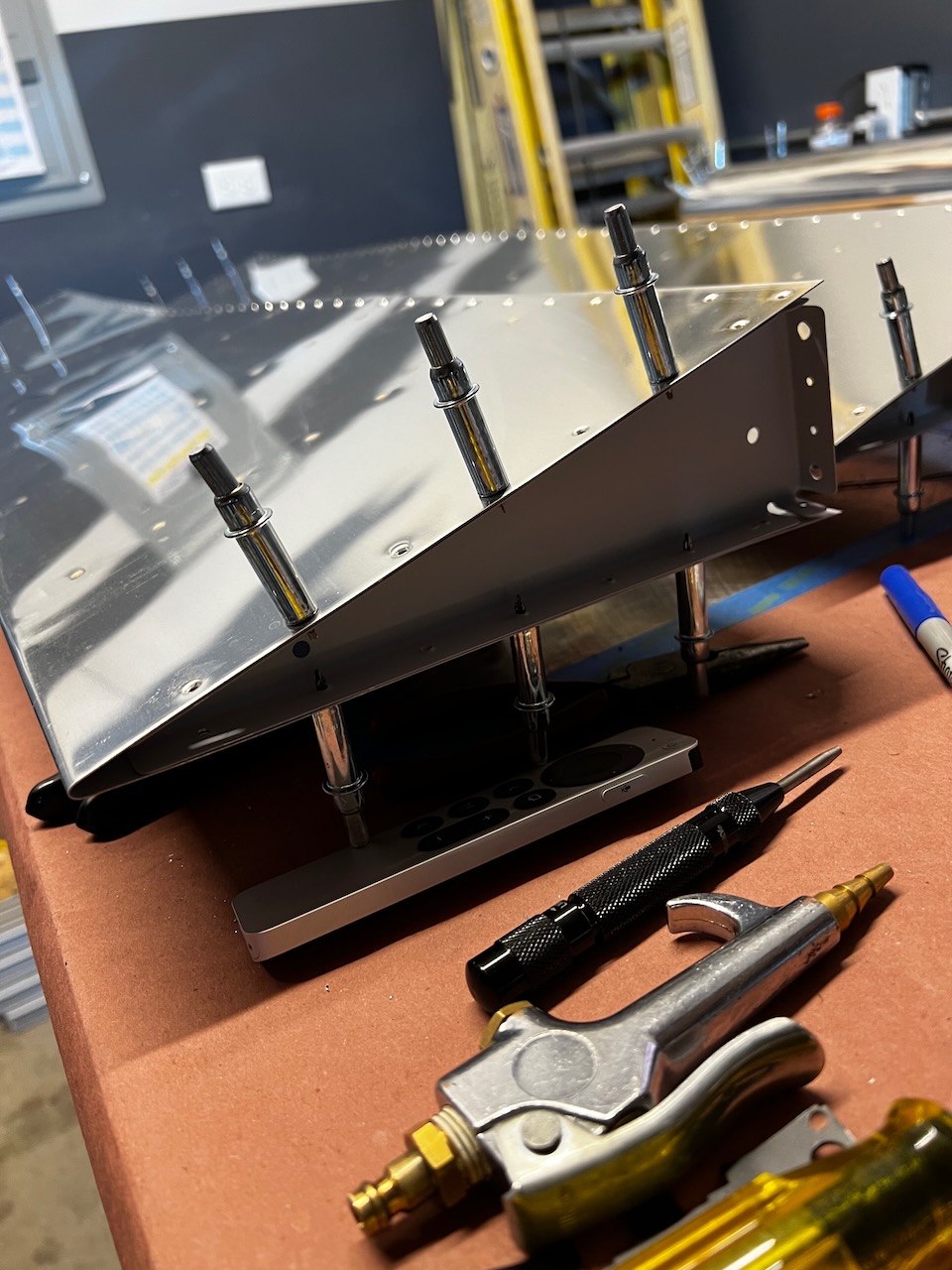
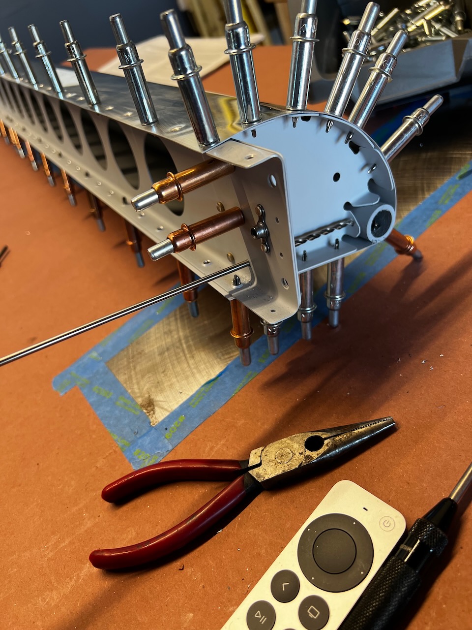
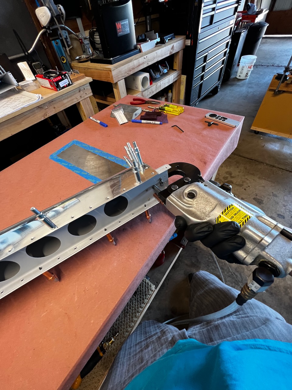
Final Assembly started
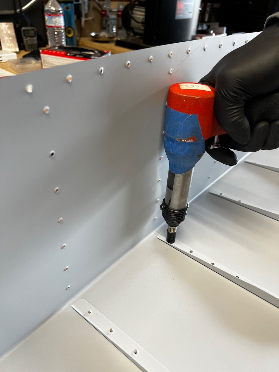
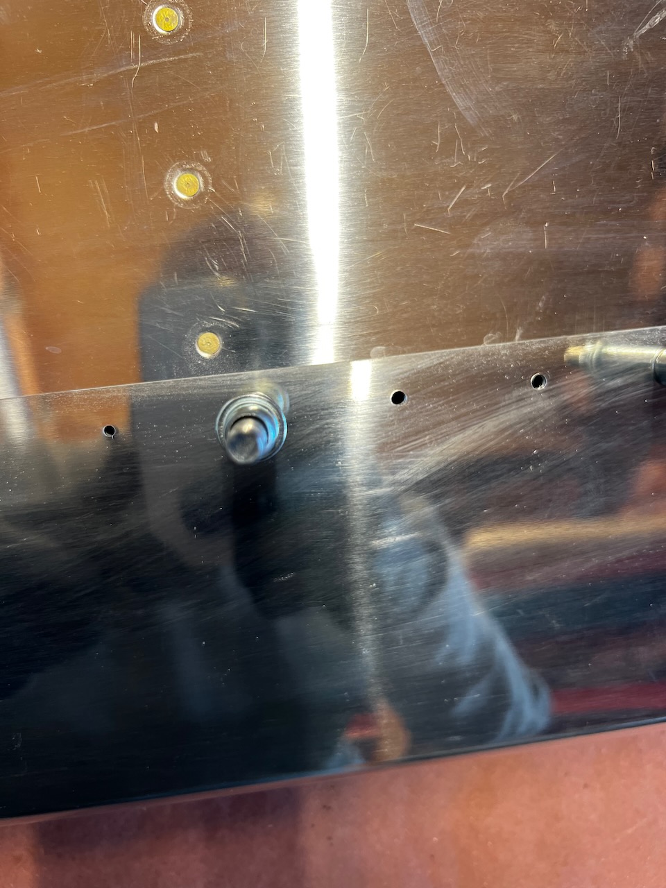
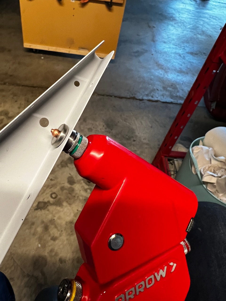
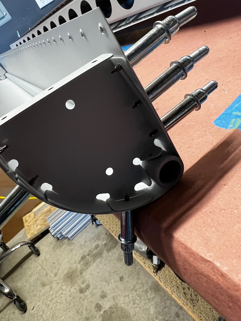
I was able to start final assembly (starting to rivet things together). It starts with attaching the counterbalance and spar to the leading edge rib.
pop riveting the counterbalance and leading edge ribs
and attaching the spar to the ribs
no going back now.
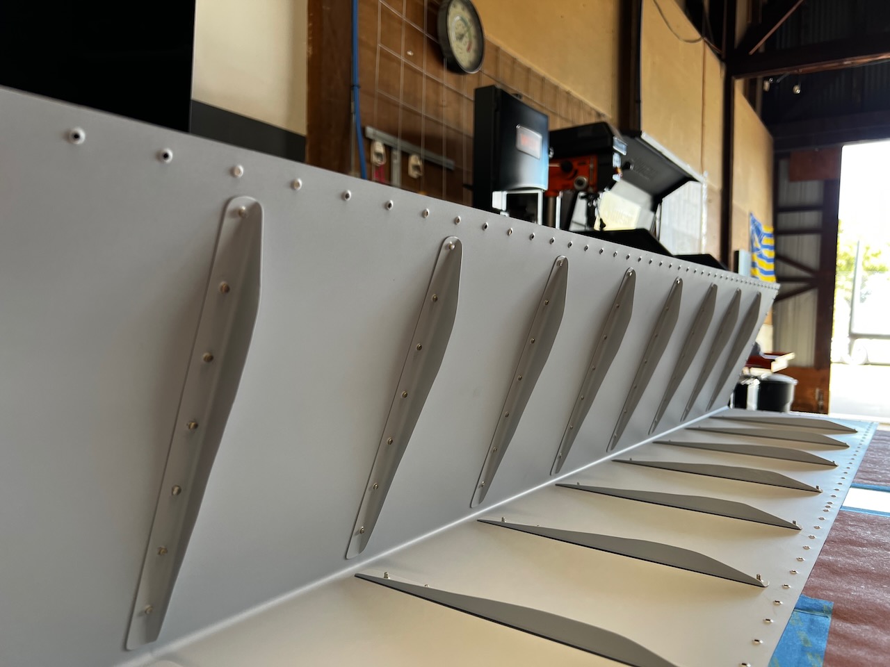
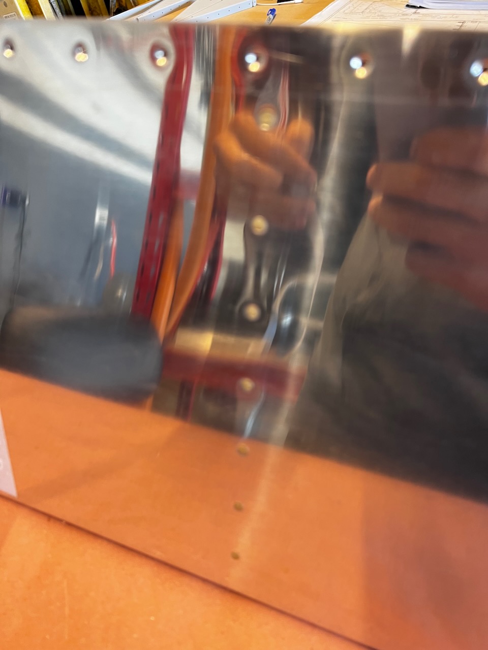
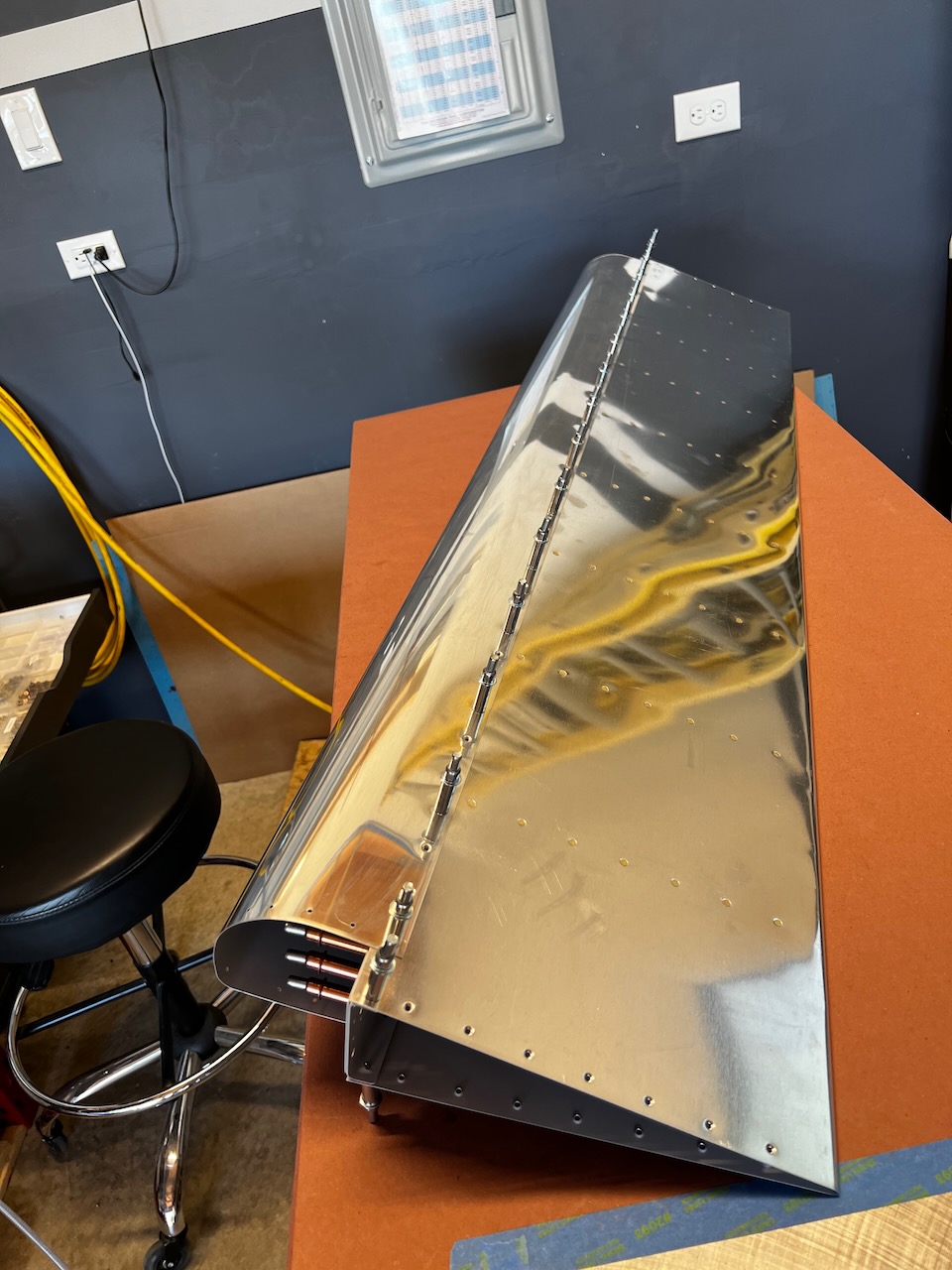
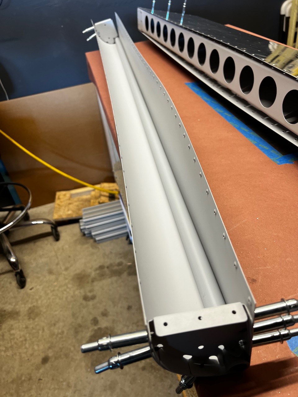
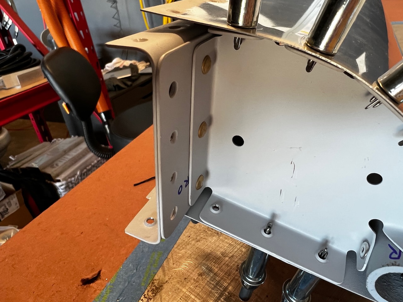
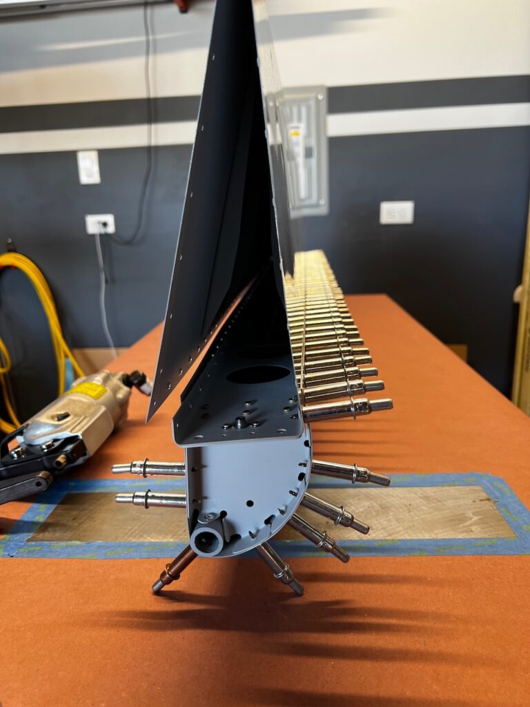
So what’s next? I somehow have to figure out a way to rivet with a bucking bar all of the top skin rivets to the spar, leading edge skin and trailing edge skin. There are a lot of rivets and it is a mighty small opening to get your arms in there. (Remember there are stiffeners in there as well). See picture below. Huh. Seems like someone with long skinny arms could help out there? Hmmmmm…I may have a plan, and his name is Giacomo! Until then, Happy Building!
we like the long 1/8″ drill bit and are wondering how many of those you go through without breaking? Also, does that red tank attached to one of the rivet guns supply air for the gun to operate?
great picture sequence………..super fun to follow.
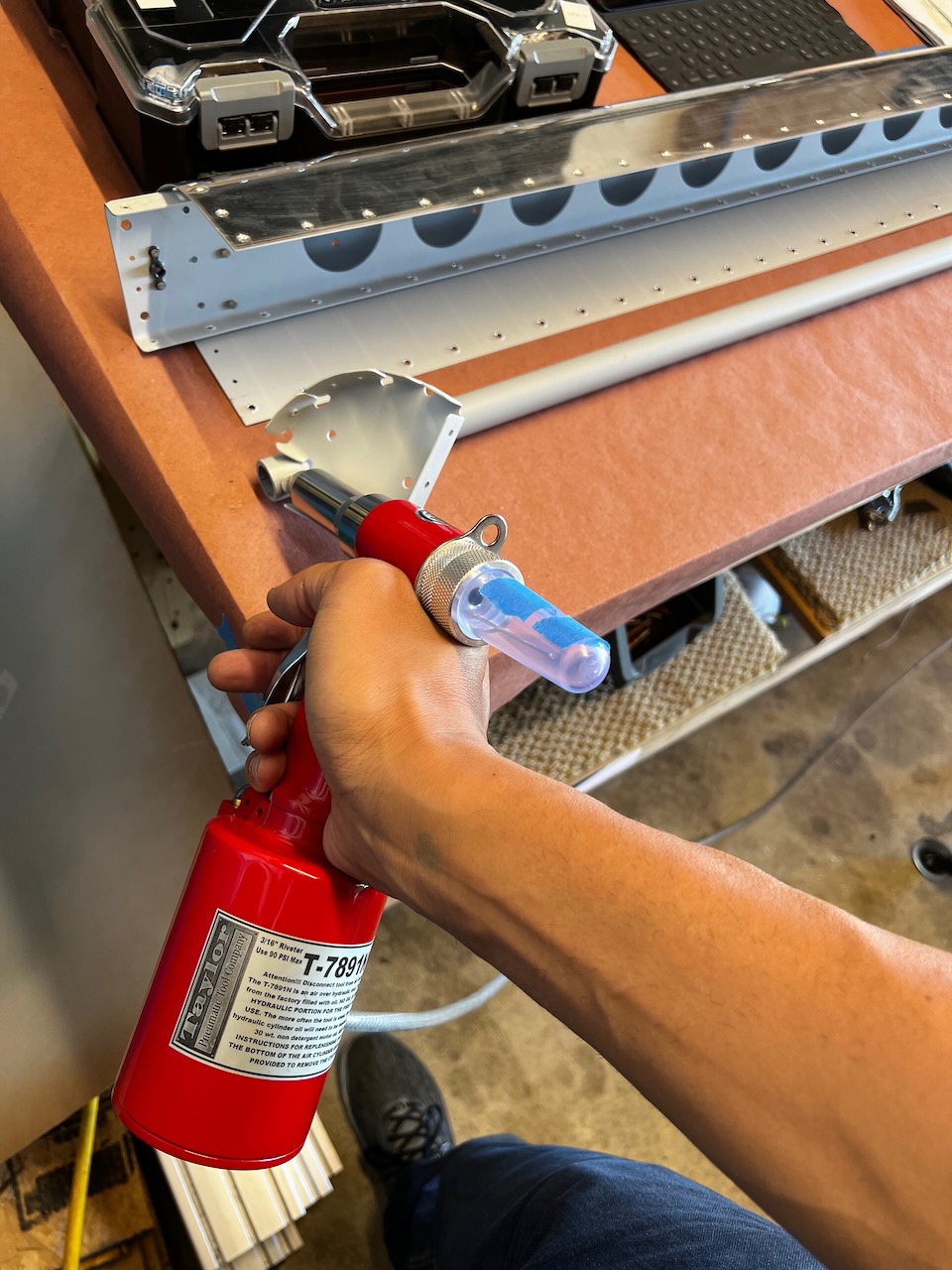
The long 1/8″ bit isn’t used that often so I haven’t broken one yet. I imagine if your use it a lot it would have a tendency to break due to its length and flexibility.
As for the red tool, that’s a pneumatic pop riveter. I’m guessing that tank is a air “capacitor” of sorts to get the massive pull when you squeeze the trigger.

4 comments
Way to progress !!! Lots of activities. NICE. Congratulations and “in bocca al lupo” on the new adventure at ABL.
Thanks dad!
we like the long 1/8″ drill bit and are wondering how many of those you go through without breaking? Also, does that red tank attached to one of the rivet guns supply air for the gun to operate?
great picture sequence………..super fun to follow.
Hey Gary!
The long 1/8″ bit isn’t used that often so I haven’t broken one yet. I imagine if your use it a lot it would have a tendency to break due to its length and flexibility.
As for the red tool, that’s a pneumatic pop riveter. I’m guessing that tank is a air “capacitor” of sorts to get the massive pull when you squeeze the trigger.