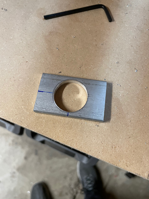
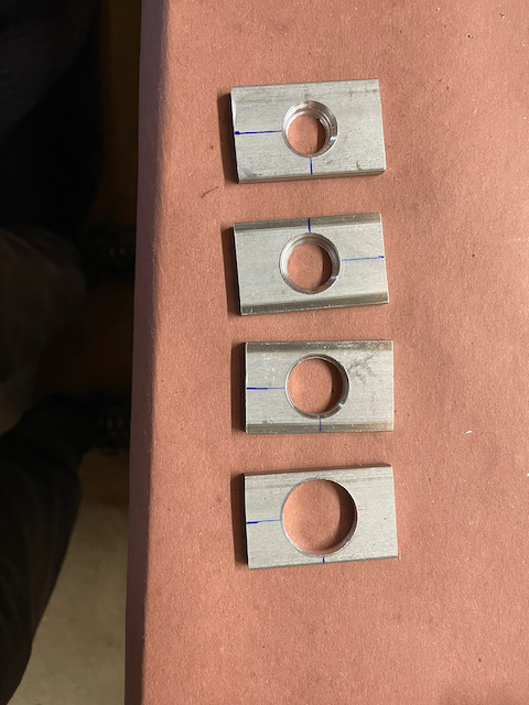
The day started with the plan of completing fabrication of the tie-down spacers. I had the cross vice setup and the unibit purchased from Amazon was set to go. The first spacer worked out great. Although a bit tough to get through the last few steps, it cut to the expected size nicely.
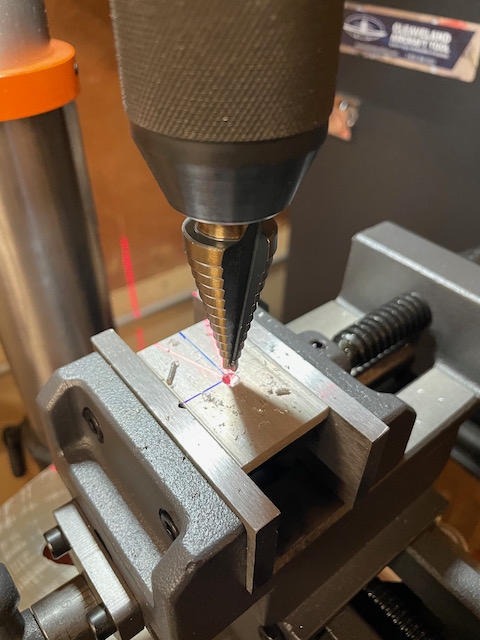
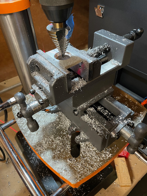
The problem was, each subsequent spacer I attempted to fabricate, the ability for the drill press to get through the metal became more and more ineffective. By the last spacer, I could barely get through 3 or 4 steps before it would seize up. I tried using drilling oil, and every RPM available to me, and it wasn’t working. After a bit of research it was my conclusion that I probably bought some really crappy bits off Amazon which just weren’t up for the job.
I went ahead and bought a well reviewed dewalt unibit, and we’ll see if that makes a big difference.
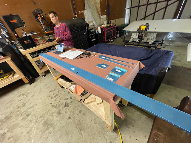
Because the session was early I didn’t want to get stuck on this so I decided to move on to Rear Spar assembly activities.
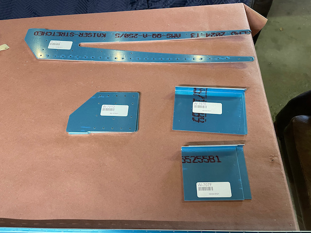
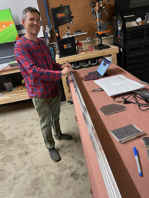
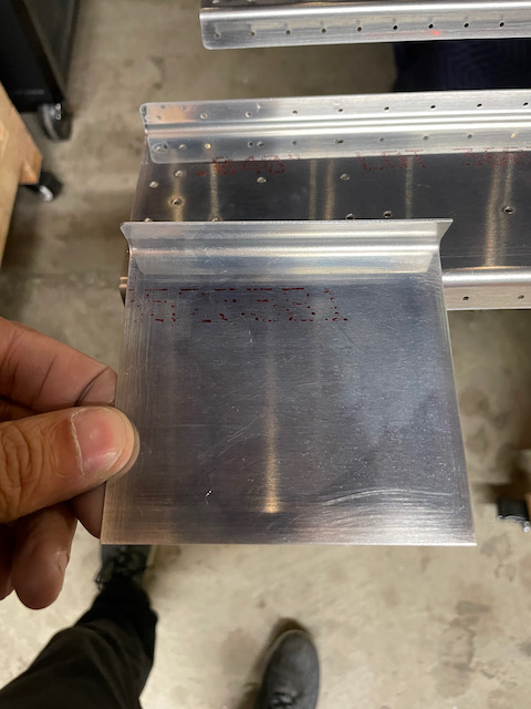
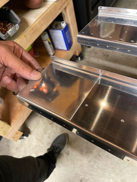
Tod came to hang out for a bit and help me inventory the rear spar parts, and start deburring all the edges. One thing to note here is that there seem to be two category of artifacts on some of these metal parts. One is clearly sharp edges that could use a deburring, but the other is not as clear. There are tiny little “ridges” that seem to be a part of the cutting process. It was not clear to me whether I needed to grind that down, or if it was ok the keep them. In the end I concluded that as long as the edges were smooth, that intent of the deburring was achieved. We used a combination of scotchbright wheels and pads to do the deburring.
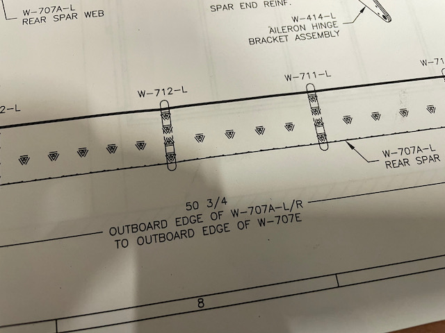
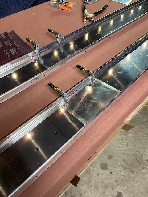
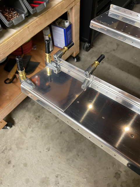
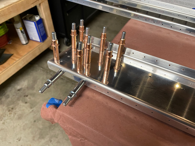
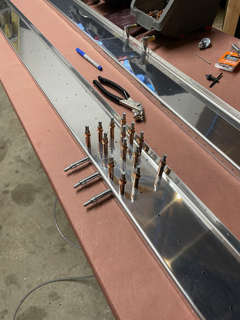
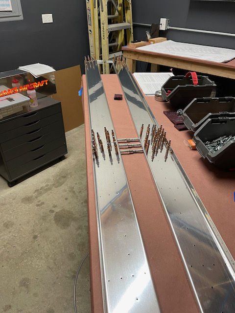
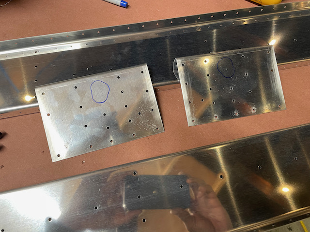
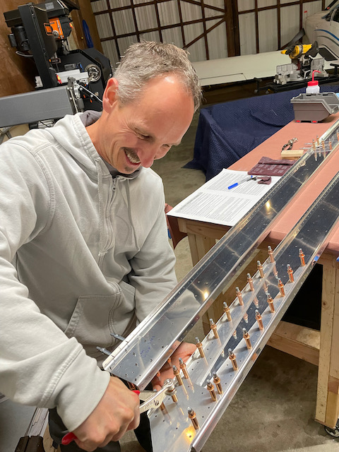
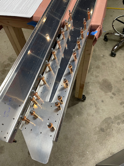
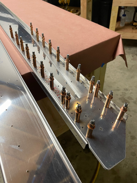
After all parts were deburred, I clamped down the W-707E and W707F stiffener plates to the main rear spar part (W-707A), and match drilled the webbing holes to #30 holes, and the flange holes to #40. Clekos were used extensively to keep things aligned as we drilled all the holes. One of the gotchas was finding the measurement for where the W-707E stiffener should go. (Hint: it’s in the plans view of DWG 10A).
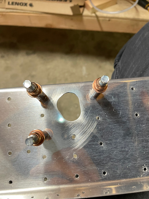
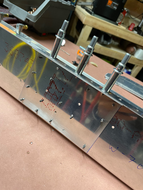
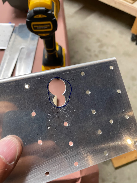
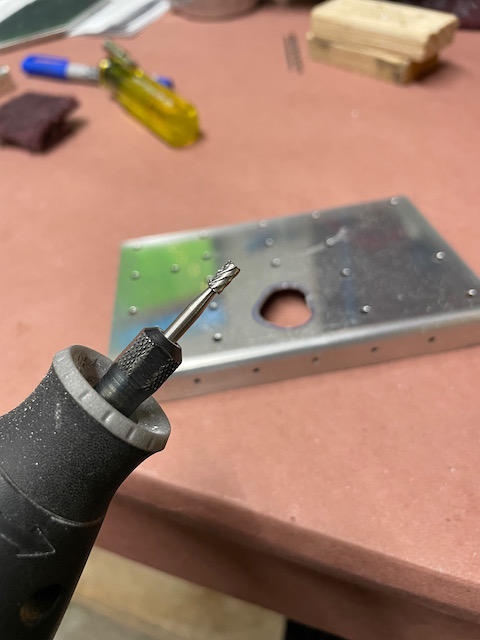
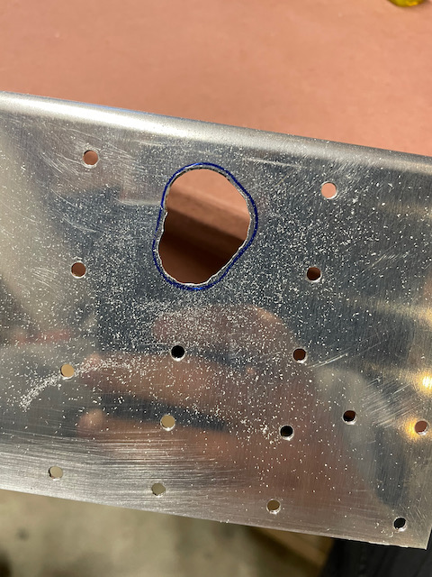
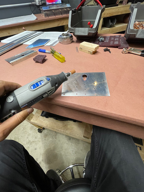
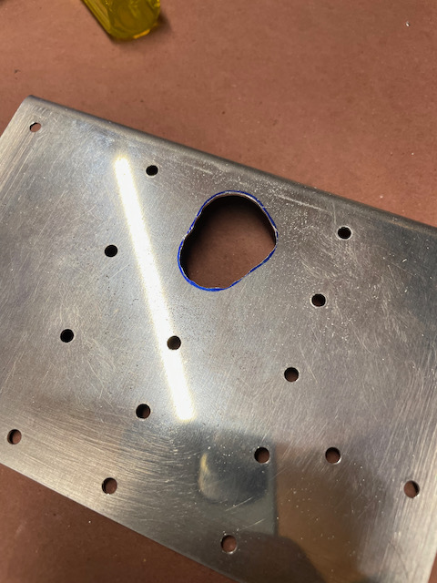
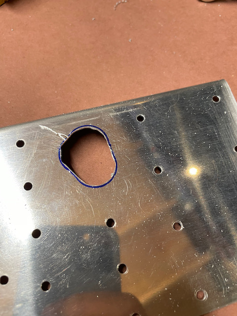
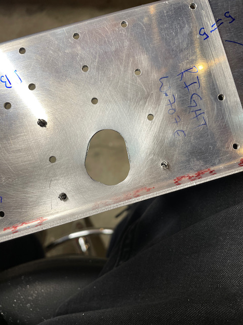
The next step took a lot of the rest of the evening, which was to make the odd looking hole shape in the center stiffener for the Aileron actuator rod. I used a combination of unibit drilling, dremel bits for refining the holes, and scotchbright to finish it off. I’m happy with how each of the holes turned out.
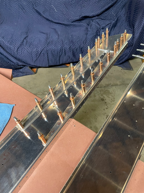
Before cleaning up, I cleko’d on the inboard fork and doubler plate to be ready for final hole size drilling tomorrow. Thorsten, my hangar neighbor came by and after catching up, he helped me cleko up some of the doubler plates.
Besides the Dodgers winning the wildcard game, it was a great night!