Since the right tank has a flop tube installed for inverted flight, the plans call for a slight modification of where the fuel sender goes. Rather than installed in the pre-drilled inboard rib access cover, I needed to create a new mounting location within the second bay area of the baffle. This seemed like a relatively simple job since I could use the spare access cover as a template. Little did I know….
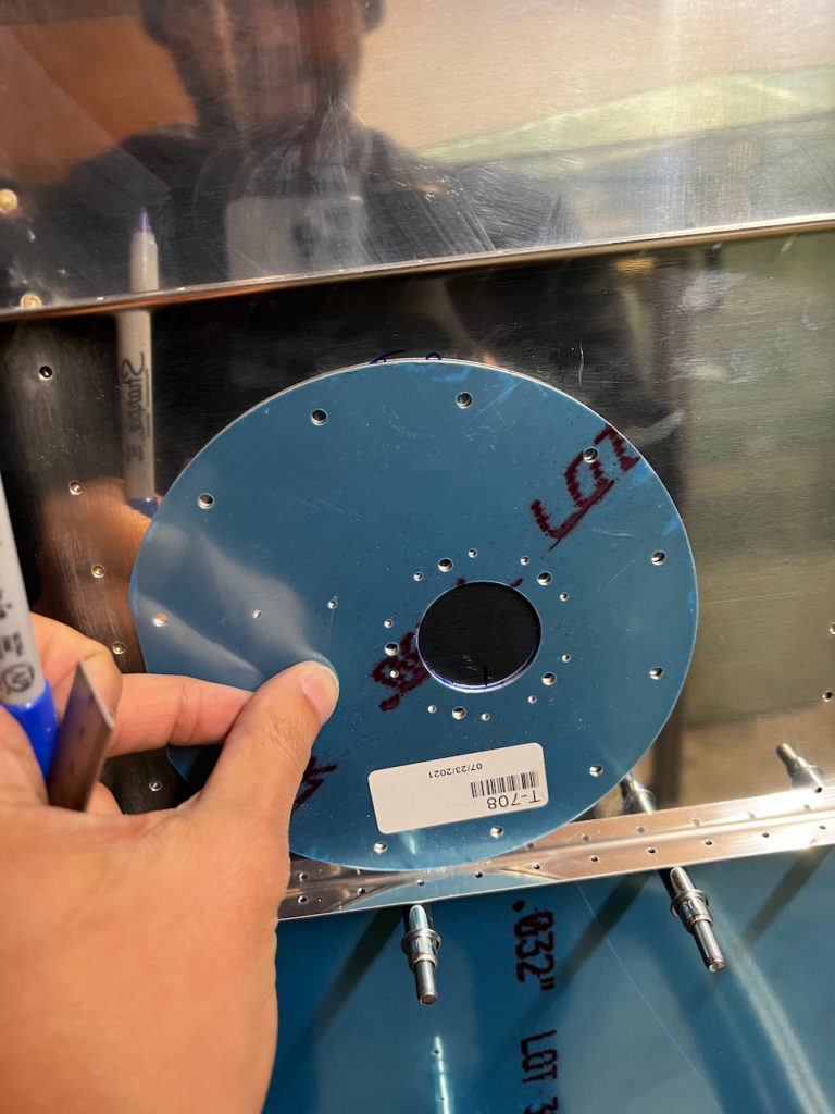
using the spare T-708 cover as a template on the baffle
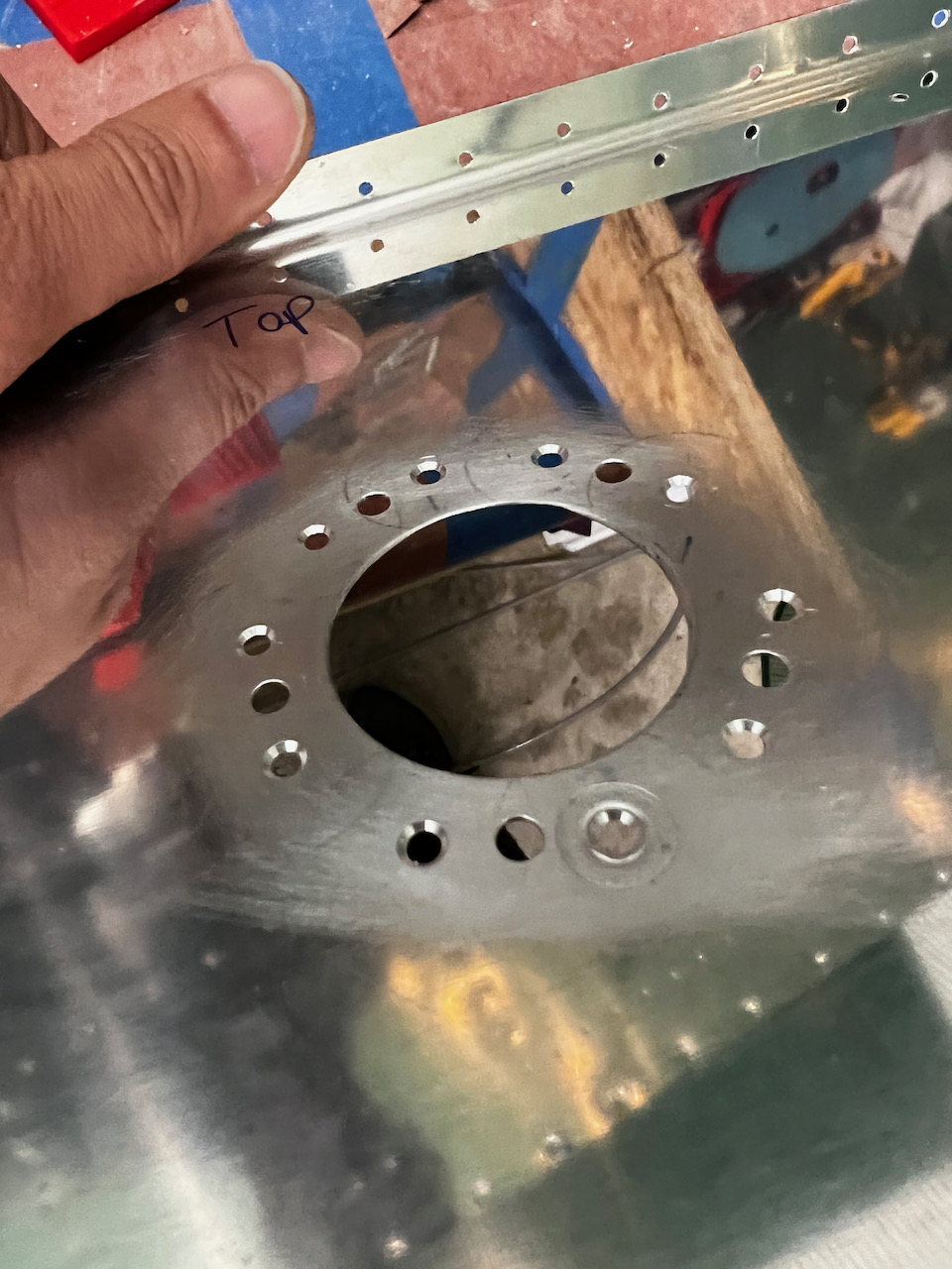
After marking the right location, I drilled out the nut plate holes, and got a 1.5″ hole saw bit to cut out the larger hole. Test fit looked great, and and after installing the nut plates, the fuel sender looked like it was going to install nicely.
making sure hole looked good
nutplate holes drilled using template
finding center on larger sender unit hole
fits great!
countersinking for nutplates
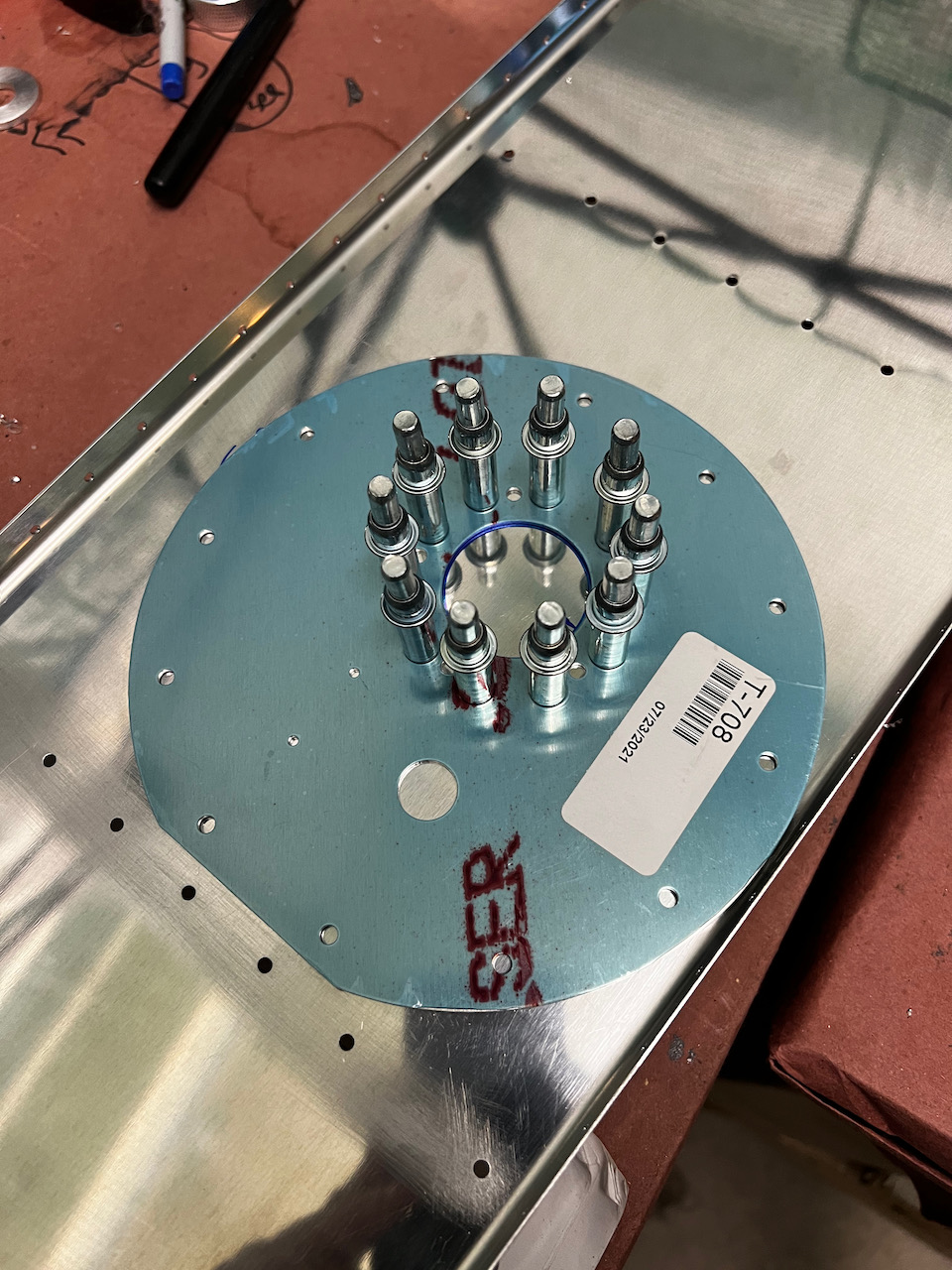
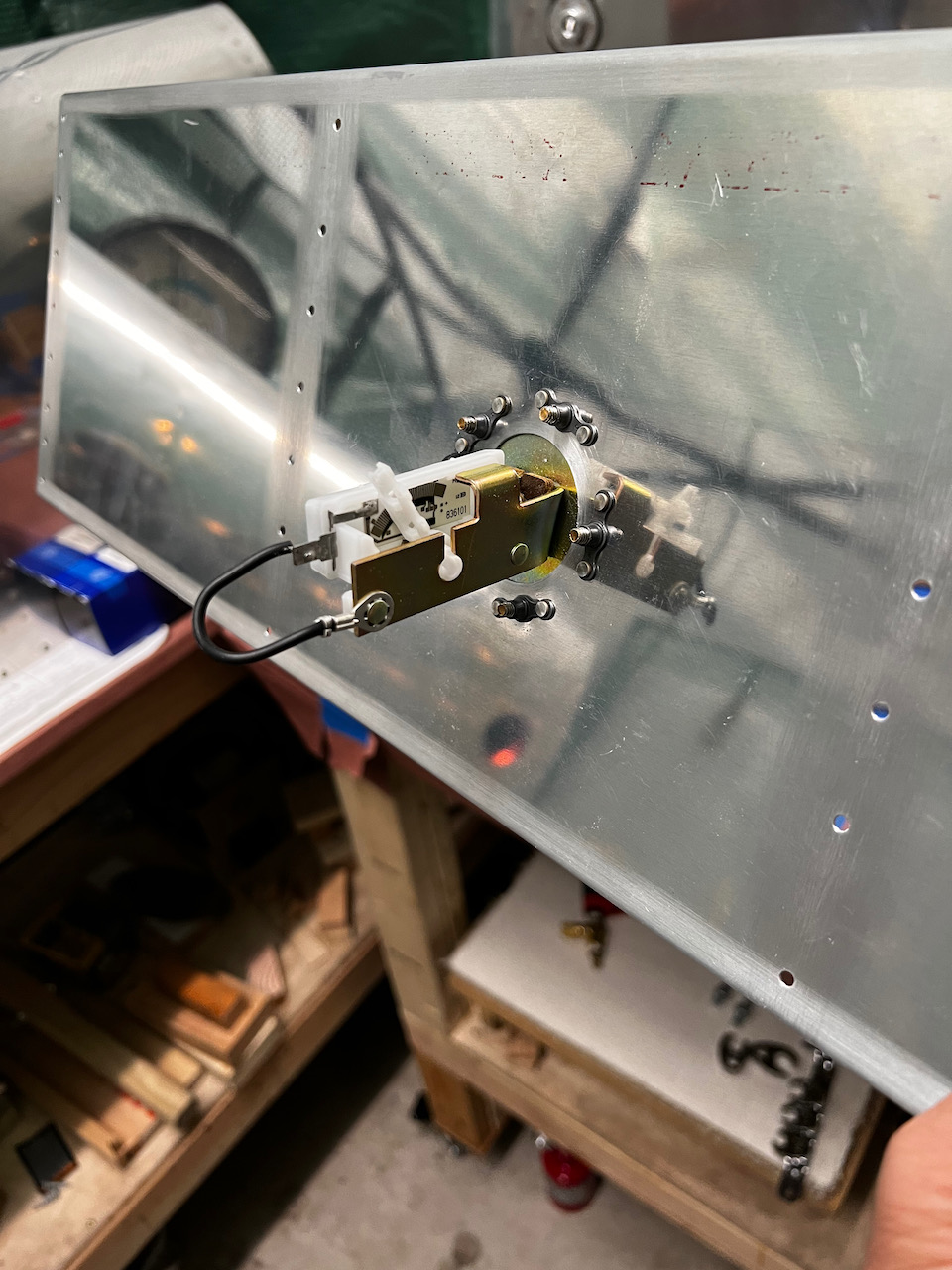
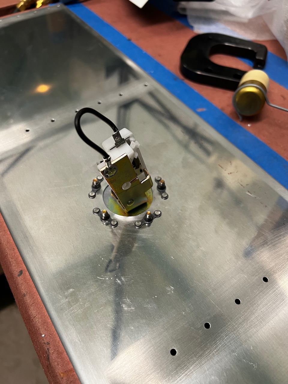
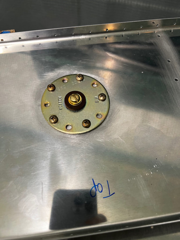
test install also looked great!
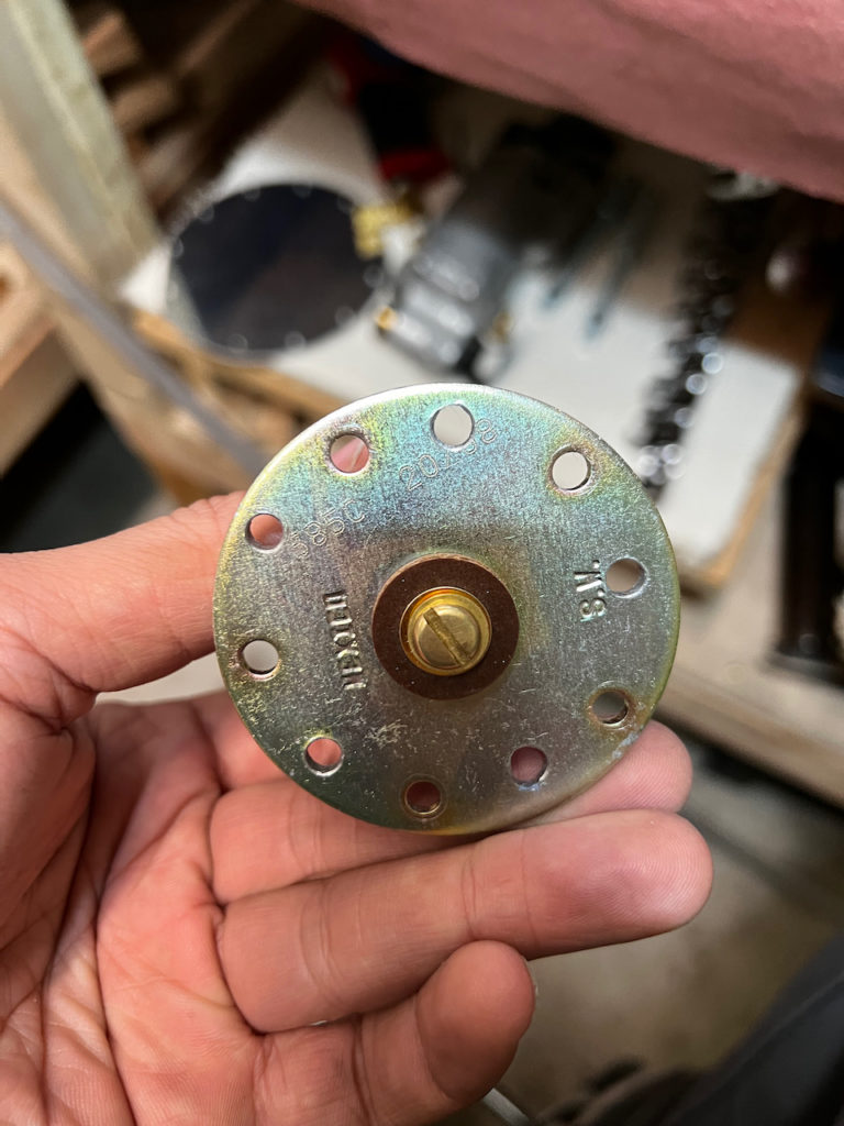
Nutplate view
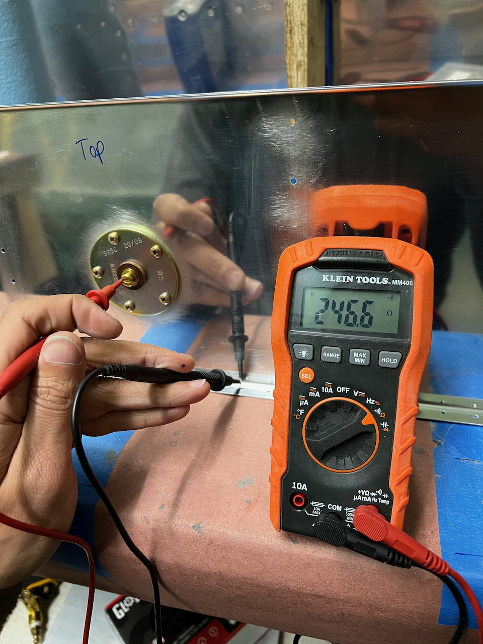
resistance test passed!
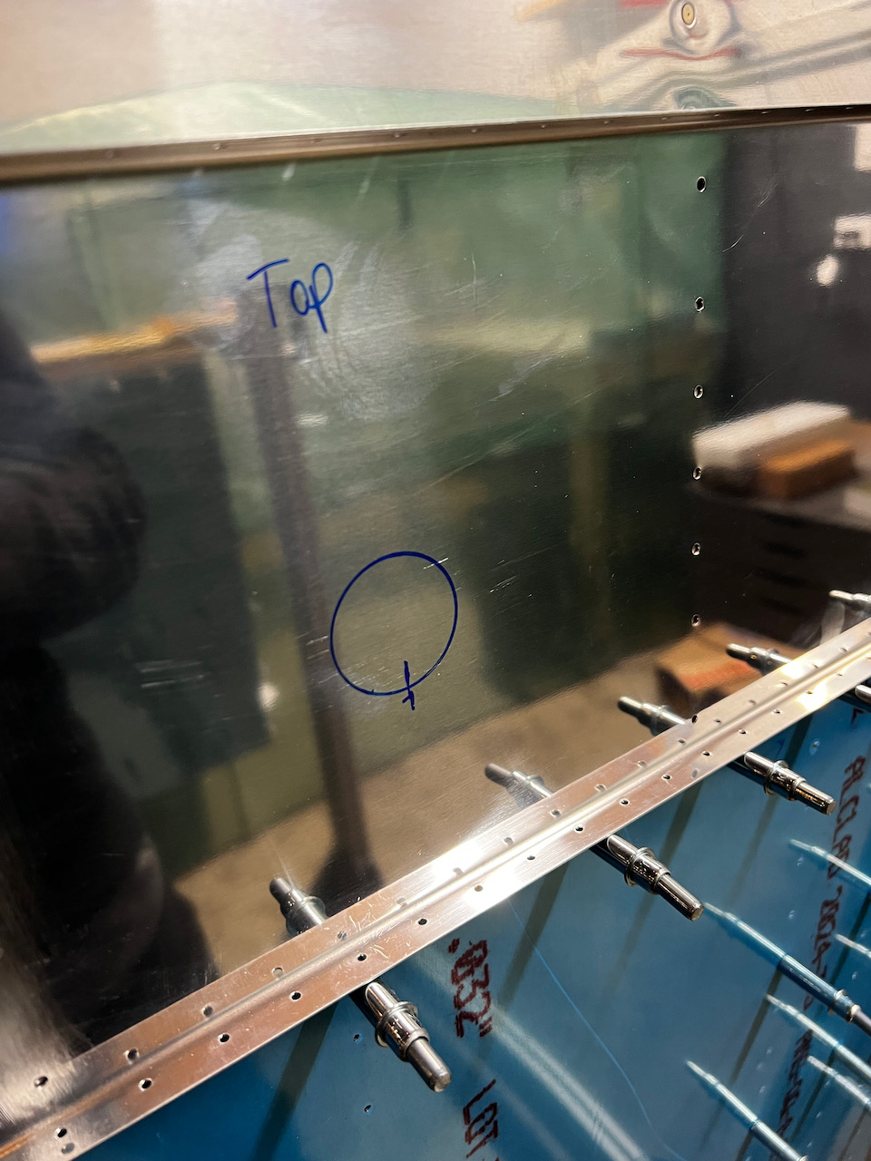
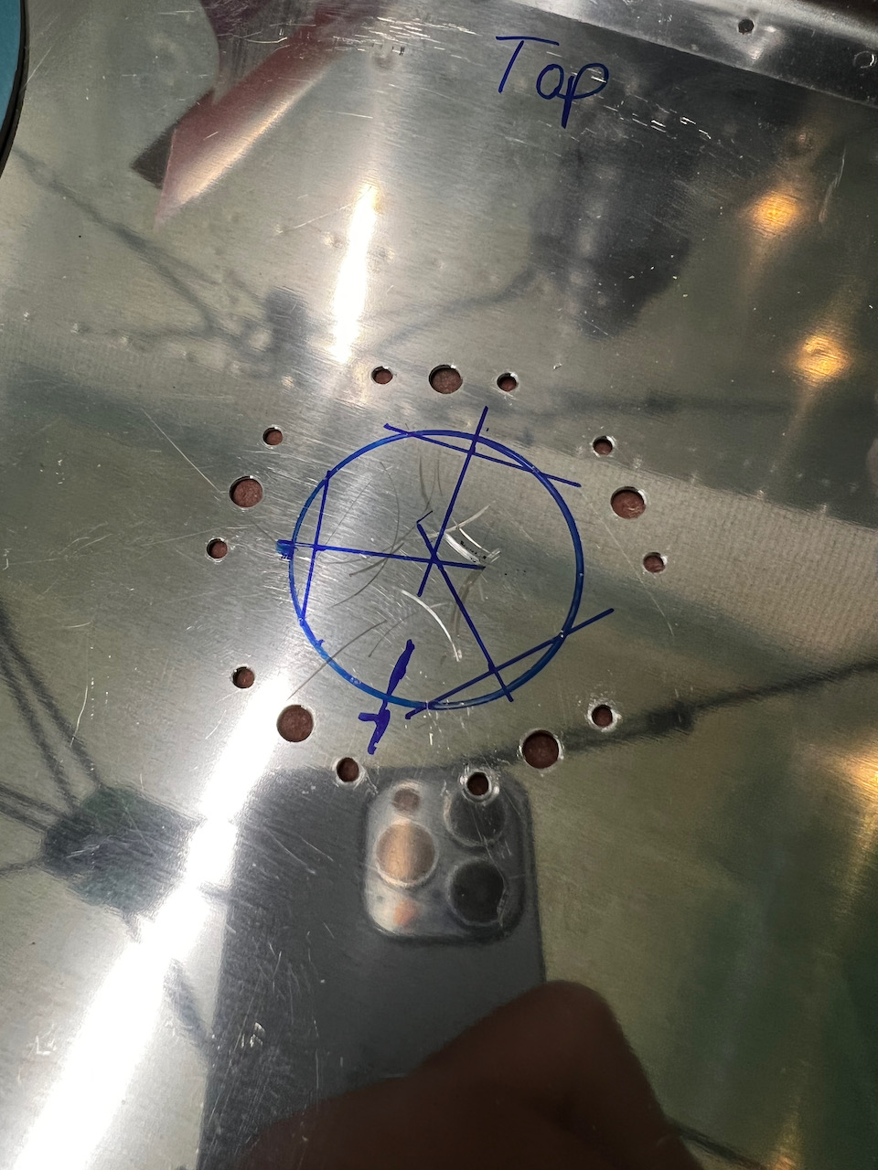
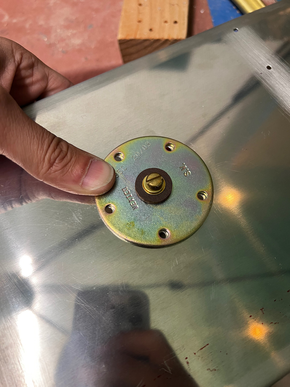
Next up I tested the install of the baffle into the tank. When I did, something looked off and it hit me immediately. I INSTALLED THE SENDER UPSIDE DOWN! AAAAHHHHHHHHHH! I realize now that when I marked “top” on the baffle during an earlier step, I had oriented the baffle against the left tank, instead of the right tank. That screwed everything up. Shoot! We just turn the sender unit around right? Nope. The screw pattern of the base pate is not symmetrical so the hole pattern in the baffle was exactly opposite what I needed. Surely we can rotate the fuel sender to twist the base and re-orient it that way right? Nope. The base is well anchored to the rest of the assembly, and I was worried I might break something. Easy then, I’ll just order a new fuel sender unit that is designed to work with my screw pattern right? Nope. I couldn’t find a version of this send with that screw pattern. UGH. Am I going to need to order a new baffle, wait 2 weeks, re-prep everything and try again? UGH. There’s got to be a better way. Well, after quite a bit of cursing, and mulling over possible solutions, I landed on re-drilling the hole pattern on the sender base plate to match the orientation I needed. There is definitely enough material to handle this correction, and the sender unit doesn’t bare any structural weight, so shouldn’t be stressed anyway. Although there are only a couple pictures of the final results, it was a total pain in the butt, and probably took me 2+ hours to complete. You can see that the holes aren’t perfect because getting the template to match up properly was extremely difficult with the form factor of the sender unit so I had to shape some of the holes to get everything to work.
recovered successfully!
clearly that "Top" marking was not correct
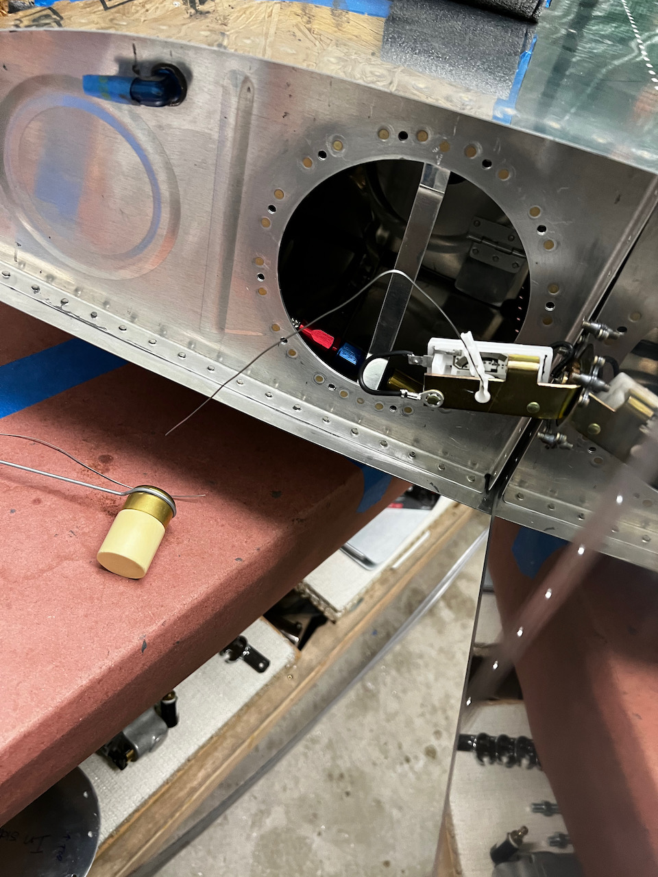
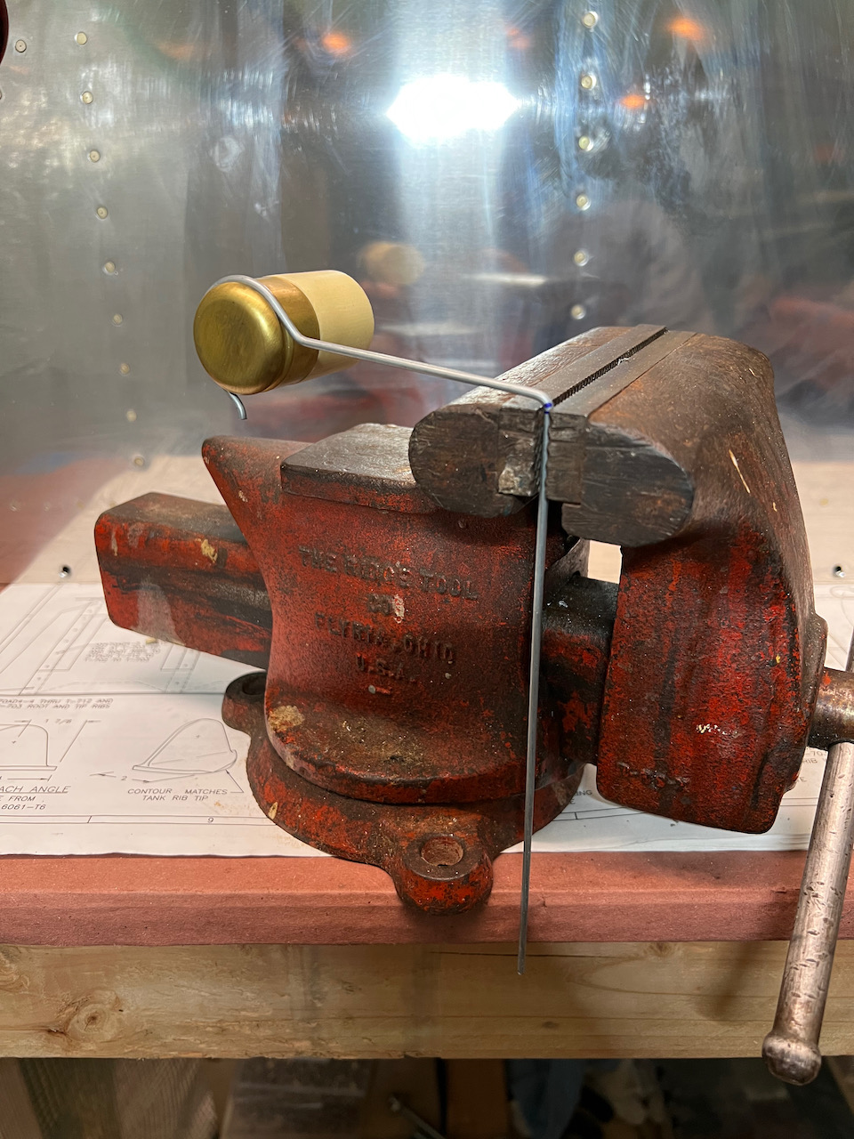
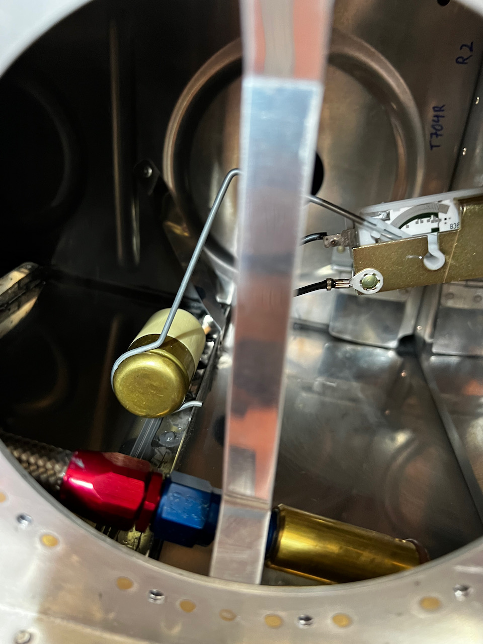
Whew! Although it was a frustrating correction to make, I’m glad I was able to recover, and I moved on to bending the fuel tank float wire. Since I wasn’t going to be able to test the wire easily, I used some safety wire to built a template a do a bit of fiddling before bending the real wire. I then used the first bay of the tank to test the final fit, using the access port to evaluate fit (since the bay profiles of 1 and 2 are the same). I couldn’t really figure out a way to get the float to end up anywhere except right over the stiffener, and so the float will sit a touch higher that it’s called out for in the non-inverted tank. It sits about 1/4″ instead of 1/16″ above the bottom of the tank. Obviously this will inaccurately read empty early, but this airs on the conservative side so I’m ok with it. Plus….all I need to do is go inverted and the tank will read full…:).
testing basic fit and shape using safety wire as a template
Bending final version
distance is a bit much, so will read empty a touch early.
With that near disaster out of the way, and the extra sealant arriving on Saturday, There’s not much left to do on the tanks but wait until the big pressure test. I may end up doing it Friday night, but otherwise early Saturday morning. I’ll be sure to report back as soon as the results are in but until then, Happy Building!

1 comment
Nice recovery. That was real good thinking. GO Paolo GO. 🤗