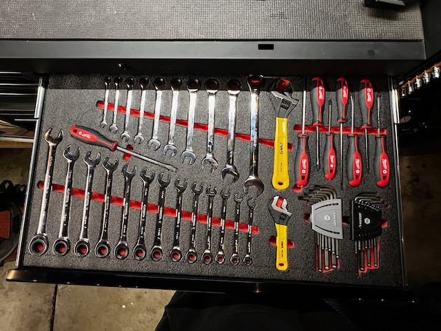
I had a nice long session today nearly completing the first drawer of kaizen foam, and then moved back to airplane building. After 1.5 hours I had finished as much as I could on the first drawer. There is a little bit of space left in the upper left corner, but I want to be thoughtful about what I put there. Since this drawer is going to be a “wrenches & drivers” drawer, I don’t want to put something random there. Here’s where it is so far.
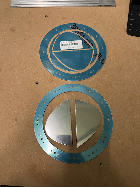
After that I spent the rest of the session working on the attach angles for the fuel tank inboard ribs. This requires fabrication from raw aluminum angle. The end result should be a reinforced wing rib which will eventually attach to the fuselage. To do this I started by using the T-710 part as a template to trace the rib shape onto the angle.
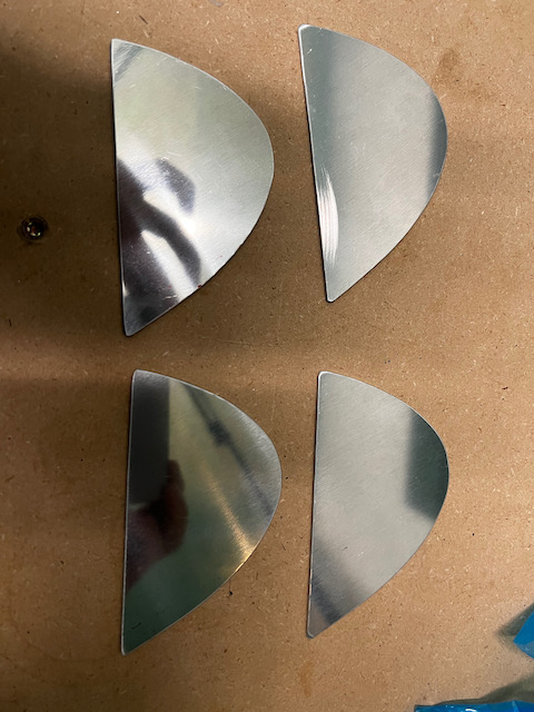
cutting out the T-710 parts
ready to be used for template tracing
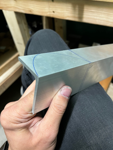
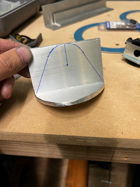
traced on to the aluminum angle
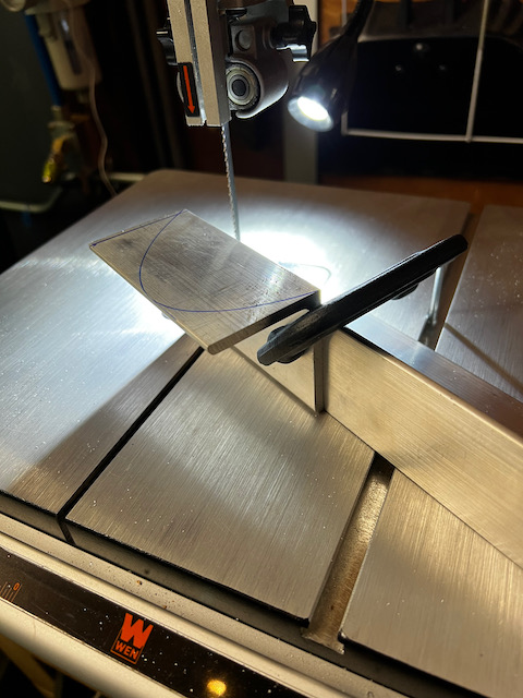
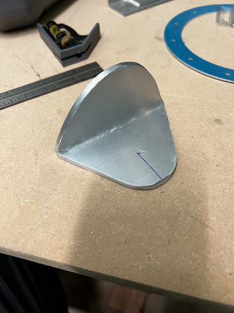
Once traced, I cut out the rib side using the bandsaw, and then using the plans marked out the radius of the attach side of the piece. It required a 1″ radius at the mid point of the piece. Fairly simple to mark out and cut. On some of the cuts, I clamped the angle so that I could cut using the outside trace a marked (see picture below).
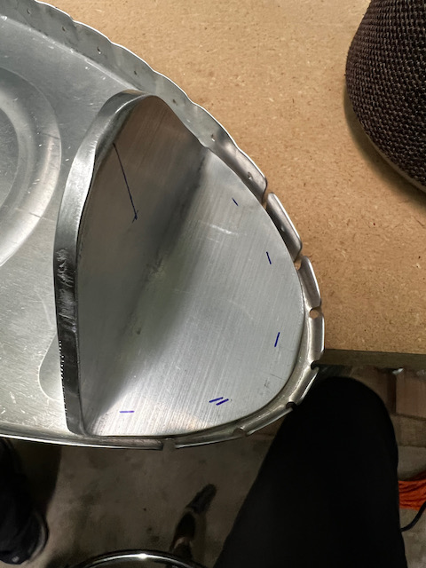
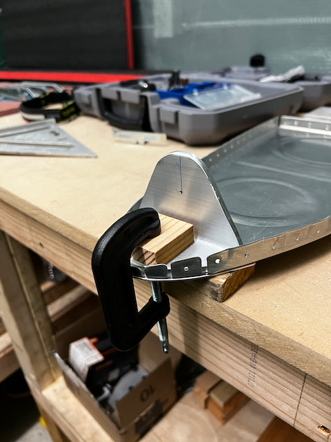
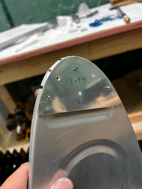
Next, I needed to mark the rivet holes. The plans don’t give you a specific measurement for these, but I did want to make sure I had appropriate edge distance. I used a ruler to mark out the distances, and then eyeballed appropriate locations for the holes. After clamping everything together (the T-705, the wing rib, and the T-710), I drilled the locations and cleco’d as I went.
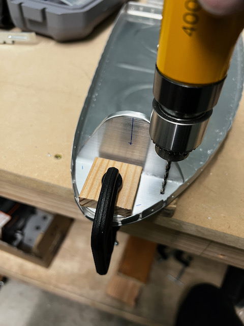
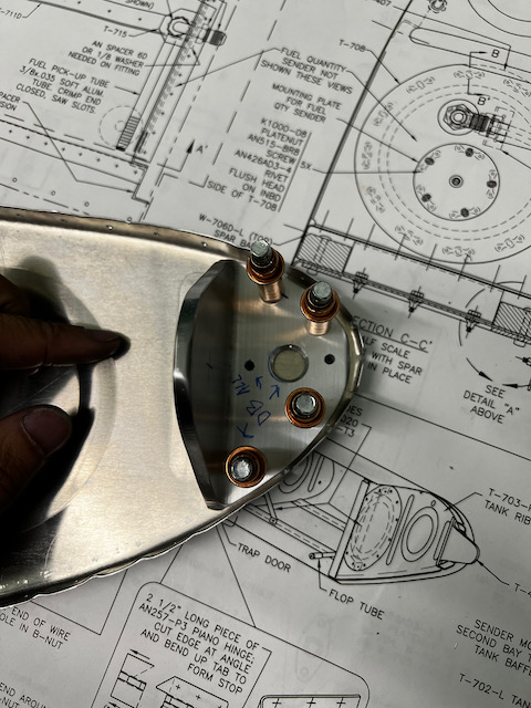
With the left side done (and deburred), I moved to the right side. It was essentially the same thing with one big exception. Since I’m going to make the aircraft fully aerobatic, I need to have at least one tank that can operate inverted. To do this you have to install a “flop tube”, which allows the fuel pickup to “flop” to the top of the tank when inverted. This requires a hole through the T-705 angle. Care must be taken to ensure you have edge distance from all holes. I spent a little extra time marking the holes, and then drilled the rivet holes as well as the fuel line hole. Since the material is so thick, I wasn’t able to use the unibit to get all the way through, so tomorrow I’ll need to pick up a 9/16″ drill bit to finish it off. That being said, It’s pretty much ready to go, and tomorrow I’ll finish that task.
Next up is using the fly cutter to cut out the large access holes in the inboard tank ribs. Until then, Happy Building!
1 comment
Nice implementation of the Kaizen foam. Fully aerobatic eh😂😂😂. Sounds like the Paolo I know.
Nice work 🤗🤗